
Self-adjusting steel coil fixing flatcar

A self-adjusting, steel coil technology, applied in trolleys, motor vehicles, multi-axle trolleys, etc., can solve the problems of inconvenient production and use, inability to fix steel coils, hidden dangers of steel coils, etc., to ensure stability, ensure safety, Anti-slip effect

Active Publication Date: 2020-05-08
济南工程职业技术学院
View PDF6 Cites 0 Cited by
  • Summary
  • Abstract
  • Description
  • Claims
  • Application Information

AI Technical Summary

Problems solved by technology

[0003] The existing steel coil transportation flat car can only carry out simple stacking of steel coils, but cannot fix the steel coils, and there is a safety hazard of steel coils falling. Although some steel coils can be fixed, they can only transport steel coils with a fixed diameter. Steel coils cannot be transported for steel coils with various diameters, which causes inconvenience in production and use

Method used


Image

  • Self-adjusting steel coil fixing flatcar
  • Self-adjusting steel coil fixing flatcar
  • Self-adjusting steel coil fixing flatcar

Examples


Embodiment 1

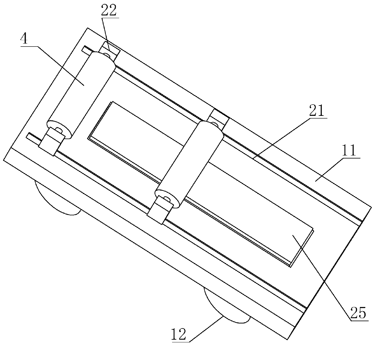
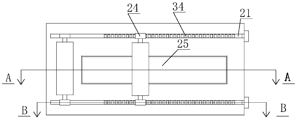
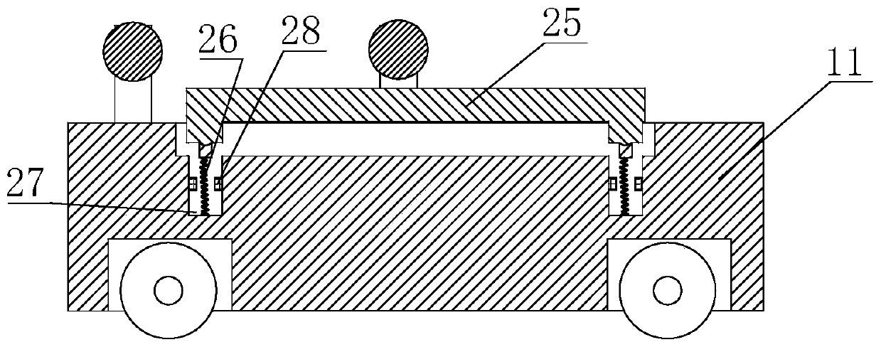
[0028] A self-adjusting steel coil fixed flat car, comprising a car body 11, the lower part of the car body 11 is provided with wheels 12, the upper surface of the car body 11 is provided with a slide rail 21 and a first limit frame 22, and the slide rail 21 is two, the first limit frame 22 is fixedly connected with the car body 11, the slide rail 21 is provided with a slider 23, the slider 23 is slidingly connected with the slide rail 21, and the upper part of the slider 23 A second limit frame 24 is provided, and the upper part of the vehicle body 11 is provided with a bearing plate 25, the bearing plate 25 is located in the middle of the vehicle body 11, the lower part of the bearing plate 25 is provided with a first spring 26, and the first spring 26 is located inside the vehicle body 11, the lower part of the first spring 26 is fixedly connected with the vehicle body 11, and the inside of the vehicle body 11 is provided with a vertical pipe 27, the first spring 26 is locat...

Embodiment 2

[0032] A self-adjusting steel coil fixed flat car. On the basis of Embodiment 1, in order to further ensure the safety of the steel coil during transportation, the side wall of the car body 11 is provided with a through hole 51, and the through hole 51 It communicates with the side wall of the slide rail 21, the through hole 51 is provided with a positioning rod 52, when the controller 29 or the electric cylinder 31 has a problem or an unexpected situation occurs, the positioning rod 52 is inserted to the position of the slider 23 In the corresponding through hole 51, the positioning rod 52 can form a position for the slider 23, which can further ensure the safety of the steel coil during transportation.


PUM


Abstract

The invention discloses a self-adjusting steel coil fixing flatcar, and relates to the technical field of steel coil transportation. The self-adjusting steel coil fixing flatcar comprises a vehicle body, wherein a sliding rail and a first limiting frame are arranged on the upper surface of the vehicle body; a sliding block is arranged in the sliding rail; a second limiting frame is arranged at theupper part of the sliding block; a bearing plate is arranged at the upper part of the vehicle body; a first spring is arranged at the lower part of the bearing plate; a vertical pipeline is arrangedin the vehicle body; the first spring is positioned in a vertical pipeline; a pressure sensor is arranged in the vertical pipeline; a controller is arranged outside the pressure sensor; a supporting plate is arranged on the upper portion of an electric air cylinder; a second spring is arranged on the upper portion of the supporting plate; a plurality of positioning blocks are arranged on the upperportion of the second spring; a limiting channel is formed in the upper portion of the supporting plate; and the positioning blocks are connected with the limiting channel in a sliding mode. The self-adjusting steel coil fixing flatcar has the beneficial effects that the distance between the limiting frames can be automatically adjusted so as to convey steel coils with different diameters.

Description

technical field [0001] The invention relates to the technical field of steel coil transportation, in particular to a self-adjusting steel coil fixed flat car. Background technique [0002] In some stamping workshops, the steel coils used to produce stamping parts are usually stored some distance away from the production site, and need to be transported in the factory, so a flatbed truck that can transport steel coils is needed; [0003] The existing steel coil transportation flat car can only carry out simple stacking of steel coils, but cannot fix the steel coils, and there is a safety hazard of steel coils falling. Although some steel coils can be fixed, they can only transport steel coils with a fixed diameter. Steel coils still cannot be transported for steel coils with various diameters, which causes inconvenience in production and use. Contents of the invention [0004] The object of the present invention is to provide a self-adjusting flat car for fixing steel coil...

Claims


Application Information

Patent Timeline
IPC IPC(8): B62B3/02B62B3/04
CPCB62B3/02B62B3/04B62B2202/025B62B2203/60
Inventor 任清华
Owner 济南工程职业技术学院
Learn More