Structure and method for reducing cell shutting pressure drop of aluminum electrolysis cell

An aluminum electrolytic cell and electrolytic cell technology, applied in the field of pressure drop structure, reducing the pressure drop of the aluminum electrolytic cell when the cell stops, can solve the problem of loss of electric energy, etc., achieve the reduction of the cell stop pressure drop, the effect is obvious, and the installation and operation are simple and easy line effect

Active Publication Date: 2020-05-08
YUNNAN ALUMINUM
8 Cites 0 Cited by

AI-Extracted Technical Summary

Problems solved by technology

The average cell voltage of a certain 300kA series electrolyzer after shutdown is about 370mV, and the average overhaul cycle after shutdown is about 35 days....

Method used

As shown in Figure 1 and 2, a certain 300kA series electrolyzer of the present embodiment has five feed column busbars, and each busbar has two short interfaces, and each short interface is respectively equipped with a temporary busbar, and the electrolytic After the slot stops, a short-circuit temporary bus 8 is installed between the short-circuit bus and the confluence large bus, so that the short-circuit bus 5 and the confluence bus are connected and conductive, thereby increasing the conductive area of ​​the short-circuit bus 5 .
As shown in Figure 3, temporary bus 6 is installed between th...

Abstract

The invention relates to a structure and method for reducing cell shutting pressure drop of an aluminum electrolysis cell. The structure comprises a plurality of temporary bus bars arranged between converging bus bars and short-circuit bus bars at short-circuit port positions, the short-circuit bus bars at the short-circuit port positions are connected with first temporary bus bars at the two endsof vertical post bus bars, the first temporary bus bars at the two ends are connected with the converging bus bars, and the converging bus bars at the cell shutting power inlet end are connected withthe converging bus bars of previous electrolytic cells through second temporary bus bars. According to the structure and method, the mounting operation is simple and easy, and the cost investment islow; and after implementation, the effect is obvious, and the cell shutting pressure drop can be greatly reduced.

Technology Topic

EngineeringStructural engineering +5

Image

  • Structure and method for reducing cell shutting pressure drop of aluminum electrolysis cell
  • Structure and method for reducing cell shutting pressure drop of aluminum electrolysis cell
  • Structure and method for reducing cell shutting pressure drop of aluminum electrolysis cell

Examples

  • Experimental program(1)

Example Embodiment

[0023] The technical solution in this embodiment will be clearly and completely described below in conjunction with the embodiments of the present invention. Apparently, the described embodiments are only some examples of the present invention, not all examples. Based on the embodiments of the present invention, all other embodiments obtained by persons of ordinary skill in the art without making creative efforts belong to the protection scope of the present invention.
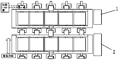
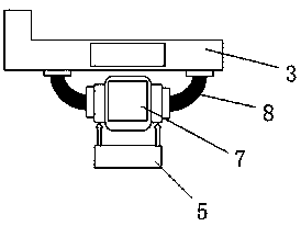
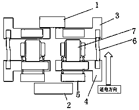
[0024] like figure 1 , 4 As shown, the structure for reducing the pressure drop of the aluminum electrolytic cell in this embodiment is specifically aimed at a certain 300kA series electrolytic cell. There are five power-feeding column busbars 7 in total. Several temporary busbars between busbars 5, such as figure 2 As shown, the short-connected busbars at each short interface position are connected to the first temporary busbars 8 at both ends of the column busbar, and the first temporary busbars 8 at both ends are connected to the busbar 3; The slot bus bars 4 are connected by a second temporary bus bar 6 .
[0025] like figure 1 , 2 As shown, a 300kA series electrolyzer in this embodiment has five power-feeding column busbars in total, each busbar has two short interfaces, and each short interface is equipped with a temporary busbar, and the busbars are short-circuited after the electrolyzer stops A short-circuit temporary bus 8 is installed between the large bus-bar for confluence, so that the short-circuit bus 5 is connected to the confluence bus for conduction, thereby increasing the conductive area of ​​the short-circuit bus 5 .
[0026] like figure 2 , 3 As shown, the two ends of the first temporary bus 8 are perpendicular to each other, and the two ends of the second temporary bus 7 are on the same horizontal line.
[0027] like image 3 As shown, a temporary bus 6 is installed between the busbar 3 of the stopped tank (that is, the overhaul tank 1) and the busbar 4 of the adjacent previous electrolyzer (that is, the normal operation tank 2), so that a part of the current can be directly passed through the stopped tank. The busbar 3 enters the next electrolytic cell where the tank is stopped, and its purpose is to increase the conductive area of ​​the short-connected busbar, reduce the resistance of the busbar, and thereby reduce the pressure drop when the tank is stopped.
[0028] like Figure 4 As shown, the method for reducing the pressure drop of the aluminum electrolytic cell for the structure of the present embodiment includes the following steps:
[0029] Step (1), clean and smooth each contact surface to ensure that the contact surface has good electrical conductivity, the fixture is installed firmly, and the crimping is reliable;
[0030] Step (2), install the first temporary busbar 8 on both sides of the third column busbar 7; symmetrically install the first temporary busbar 8 of the second and fourth column busbars; symmetrically install the first temporary busbars of the first and fifth column busbars busbar 8;
[0031] Step (3), install the second temporary busbar 6 between the busbar 3 at the feeder end of the stopped tank and the busbar 7 of the previous electrolyzer;
[0032] Step (4), when disassembling, use the reverse order of installation;
[0033] Step (5), after the installation is completed, keep the electrolytic cell control machine turned on, pay attention to the voltage change of the electrolytic cell and the operation of adjacent electrolytic cells, and report any abnormalities in time and check and deal with them;
[0034] Step (6), all installed temporary busbars must be dismantled in order before opening the slot and electrifying to prevent explosion when electrifying.

PUM

no PUM

Description & Claims & Application Information

We can also present the details of the Description, Claims and Application information to help users get a comprehensive understanding of the technical details of the patent, such as background art, summary of invention, brief description of drawings, description of embodiments, and other original content. On the other hand, users can also determine the specific scope of protection of the technology through the list of claims; as well as understand the changes in the life cycle of the technology with the presentation of the patent timeline. Login to view more.

Similar technology patents

Micromotor capable of extending voltage applicable scope

InactiveCN101908793AImprove commutation sparkEasy to install and operate
Owner:WUXI KAIXUAN MOTOR

Ozone denitration pre-sprinkling absorption device

PendingCN107854982AImprove denitrification efficiencyEasy to install and operate
Owner:HUADIAN ELECTRIC POWER SCI INST CO LTD

Lamp box structure

Owner:NANJING CHENGUANG ART ENG CO LTD

Classification and recommendation of technical efficacy words

  • Reduce cost input
  • Easy to install and operate

Garden under-forest cultivation method for Morchella

InactiveCN105917965AReduce cultivation riskReduce cost input
Owner:INST OF SOIL FERTILIZER SICHUAN ACAD OF AGRI SCI

Deoxidizing and drying agent and preparation method thereof

InactiveCN103721533AAdd new function of deoxygenationReduce cost input
Owner:广西弘耀祥科技有限公司

Forest fire alarm method based on transmission network

InactiveCN106920358Amonitor wellReduce cost input
Owner:STATE GRID FUJIAN ELECTRIC POWER CO LTD +2

Self-propelling camellia oleifera fruit-picking machine

InactiveCN102668817AEasy to install and operateGood adaptability to picking environment
Owner:CENTRAL SOUTH UNIVERSITY OF FORESTRY AND TECHNOLOGY +1
Why Eureka
Try Eureka