
U-shaped push rod for automobile electric tail-gate system

An electric and tailgate technology, applied in the direction of door/window accessories, power control mechanism, wing leaf control mechanism, etc., can solve the problems of reduced pushing and stabilizing effects, reduced service life of push rods, reduced motor torque, etc., to achieve reduction Effects of wear, prolonging service life, and reducing friction

Inactive Publication Date: 2020-05-08
江苏合泓通讯技术有限公司
View PDF0 Cites 0 Cited by
  • Summary
  • Abstract
  • Description
  • Claims
  • Application Information

AI Technical Summary

Problems solved by technology

When the motor is used for a long time, the rotor of the motor will be damaged, which reduces the torque of the motor and the service life of the push rod. After long-term rotation of the screw and the sleeve rod, the tooth pattern on the surface of the screw will wear out, causing the screw to The pushing and stabilizing effect of the sleeve rod are reduced

Method used


Image

  • U-shaped push rod for automobile electric tail-gate system
  • U-shaped push rod for automobile electric tail-gate system
  • U-shaped push rod for automobile electric tail-gate system

Examples


Embodiment Construction

[0021] The following will clearly and completely describe the technical solutions in the embodiments of the present invention with reference to the accompanying drawings in the embodiments of the present invention. Obviously, the described embodiments are only some, not all, embodiments of the present invention.

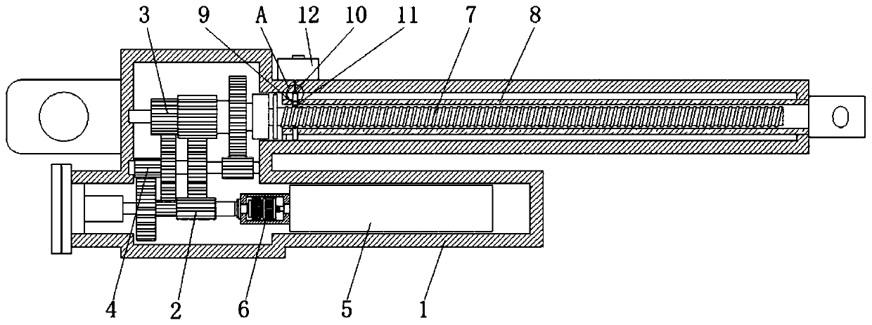
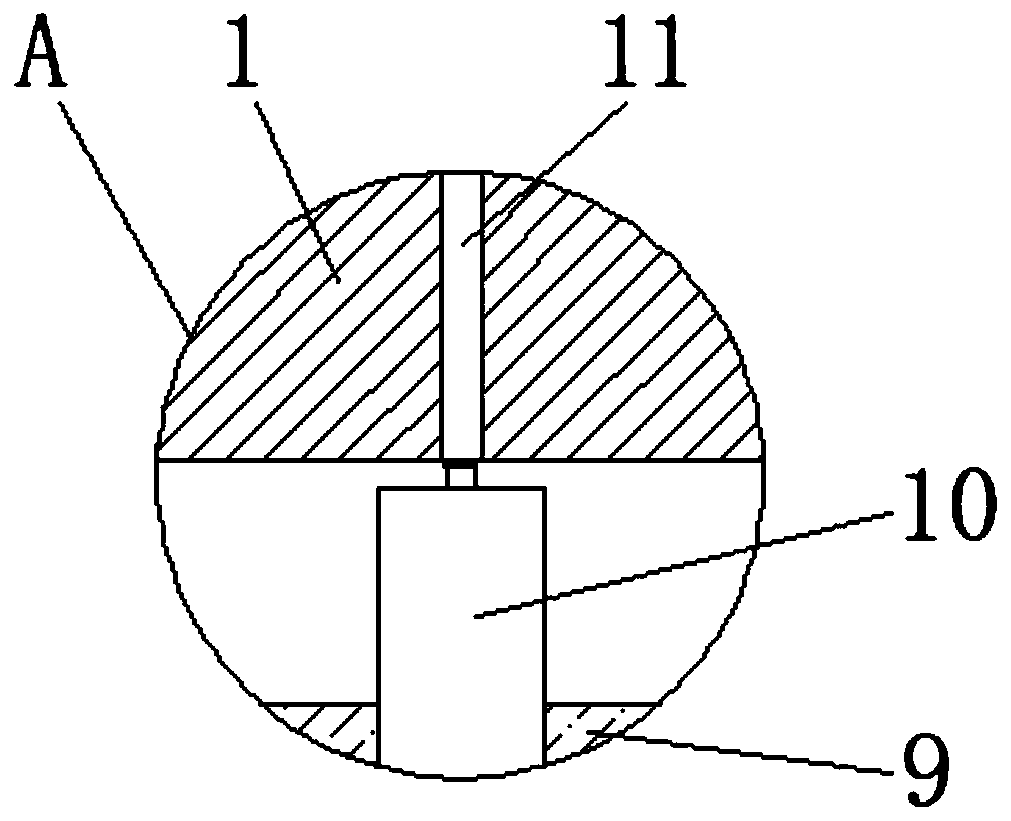
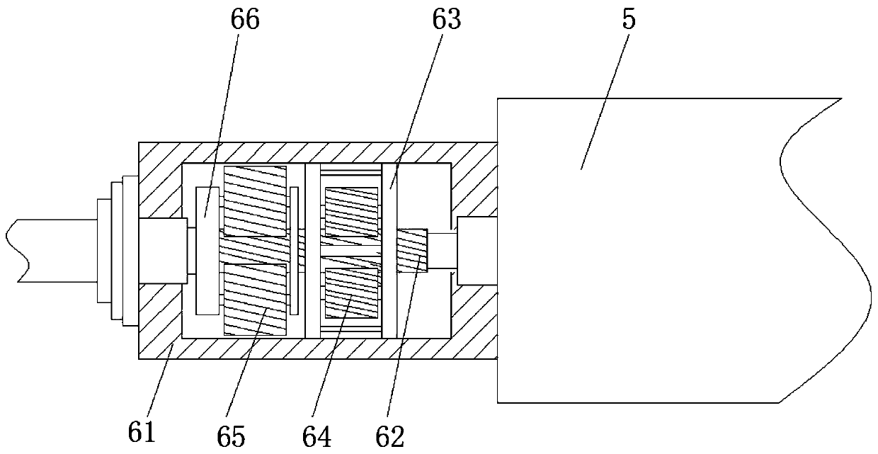
[0022] see Figure 1 to Figure 4 The present invention provides a technical solution: a U-shaped push rod used in an automobile electric tailgate system, including a casing 1, a permanent magnet motor 5 is fixedly installed inside the casing 1, and a rotating shaft of the permanent magnet motor 5 is fixedly sleeved with a transmission The device 6, the transmission device 6 includes the device body 61, the main inclined column rod 62, the installation card seat 63, the first helical gear 64, the second helical gear 65 and the swivel seat 66, the main inclined column bar 62, the installation card seat 63, the second helical gear One helical gear 64, the second helical...


PUM


Abstract

The invention discloses a U-shaped push rod for an automobile electric tail-gate system, relates to the technical filed of automobile precision instruments, in particular to the U-shaped push rod forthe automobile electric tail-gate system. The U-shaped push rod comprises a shell, a permanent magnet motor fixedly installed in the shell, a transmission device is fixedly connected to the rotating shaft of the permanent magnet motor in a sleeving mode, a driving gear group is fixedly connected to the rotating shaft of the transmission device in a sleeving mode, and the driving gear groups are engaged with a driven gear group. According to the U-shaped push rod for the automobile electric tail-gate system, after the rotating shaft of the permanent magnet motor is connected with the transmission device, the driving gear group is driven to rotate, by using the rotation inertia and centrifugal force generated by the rotation of a first helical gear and a second helical gear which are arranged in the transmission device, the torque of a main oblique column rod is auxiliarily increased, the damage to the permanent magnet motor is lowered, meanwhile the pushing force of an external sleeve pipe to a vehicle door is improved, and the supporting force of the U-shaped push rod is effectively improved.

Description

technical field [0001] The invention relates to the technical field of automotive precision instruments, in particular to a U-shaped push rod used in an automotive electric tailgate system. Background technique [0002] The push rod system of the electric tailgate of the car is composed of inner oil, outer casing, and motor gearbox assembly. The motor gearbox assembly drives the outer conduit to do reciprocating linear motion through the drive screw, and the tail box is realized under the action of the movement of the motor-driven outer casing. Therefore, the gear reduction motor of the tailgate push rod must have the characteristics of large torque. When the motor is used for a long time, the rotor of the motor will be damaged, which reduces the torque of the motor and the service life of the push rod. After long-term rotation of the screw rod and the sleeve rod, the tooth pattern on the surface of the screw rod will wear out, causing the screw rod to wear. The pushing and...

Claims


Application Information

Patent Timeline
Patent Type & Authority Applications(China)
IPC IPC(8): E05F15/622
CPCE05F15/622E05Y2900/548
Inventor 许海明
Owner 江苏合泓通讯技术有限公司
Learn More