
A kind of hard stone airborne splitting machine

A splitting machine and stone technology, which is applied in the field of hard stone airborne splitting machines, can solve the problems of high cost, reduced equipment service life, waste of resources, etc., achieve good splitting effect, improve adaptability, increase The effect of service life

Active Publication Date: 2020-11-10
徐州天顾科技有限公司
View PDF6 Cites 0 Cited by
  • Summary
  • Abstract
  • Description
  • Claims
  • Application Information

AI Technical Summary

Problems solved by technology

[0003] 1. Before splitting, the existing splitting machine needs to adjust the position of the splitting gun according to the direction of splitting, because the splitting block can only produce force on both sides, so it is a pre-placed time before splitting. It will cost more, and at the same time, the splitting effect caused by this is only on one line, without making all the force of the hydraulic device act on the stone. On the one hand, the splitting effect is not good or the splitting direction does not meet the requirements. On the other hand, it causes a waste of force, and the generated hydraulic pressure is very large, which is a waste of resources when it is not fully utilized.
[0004] 2. There will be a space between the wedge and the splitting block of the splitter when they are opened and closed, and small stones will be easily stuck in, so that the subsequent splitting will cause wedges or splitting blocks Deformation caused by stones stuck in the middle can cause equipment damage, etc., which reduces the service life of the equipment and increases the cost of splitting

Method used


Image

  • A kind of hard stone airborne splitting machine
  • A kind of hard stone airborne splitting machine
  • A kind of hard stone airborne splitting machine

Examples


Embodiment Construction

[0024] The following will clearly and completely describe the technical solutions in the embodiments of the present invention with reference to the accompanying drawings in the embodiments of the present invention. Obviously, the described embodiments are only some, not all, embodiments of the present invention. Based on the embodiments of the present invention, all other embodiments obtained by persons of ordinary skill in the art without making creative efforts belong to the protection scope of the present invention.

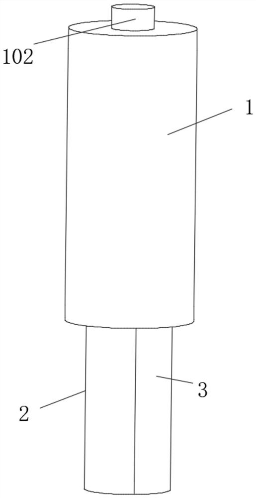
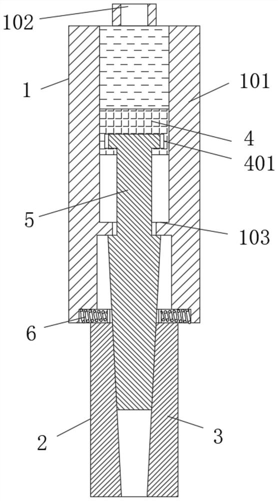
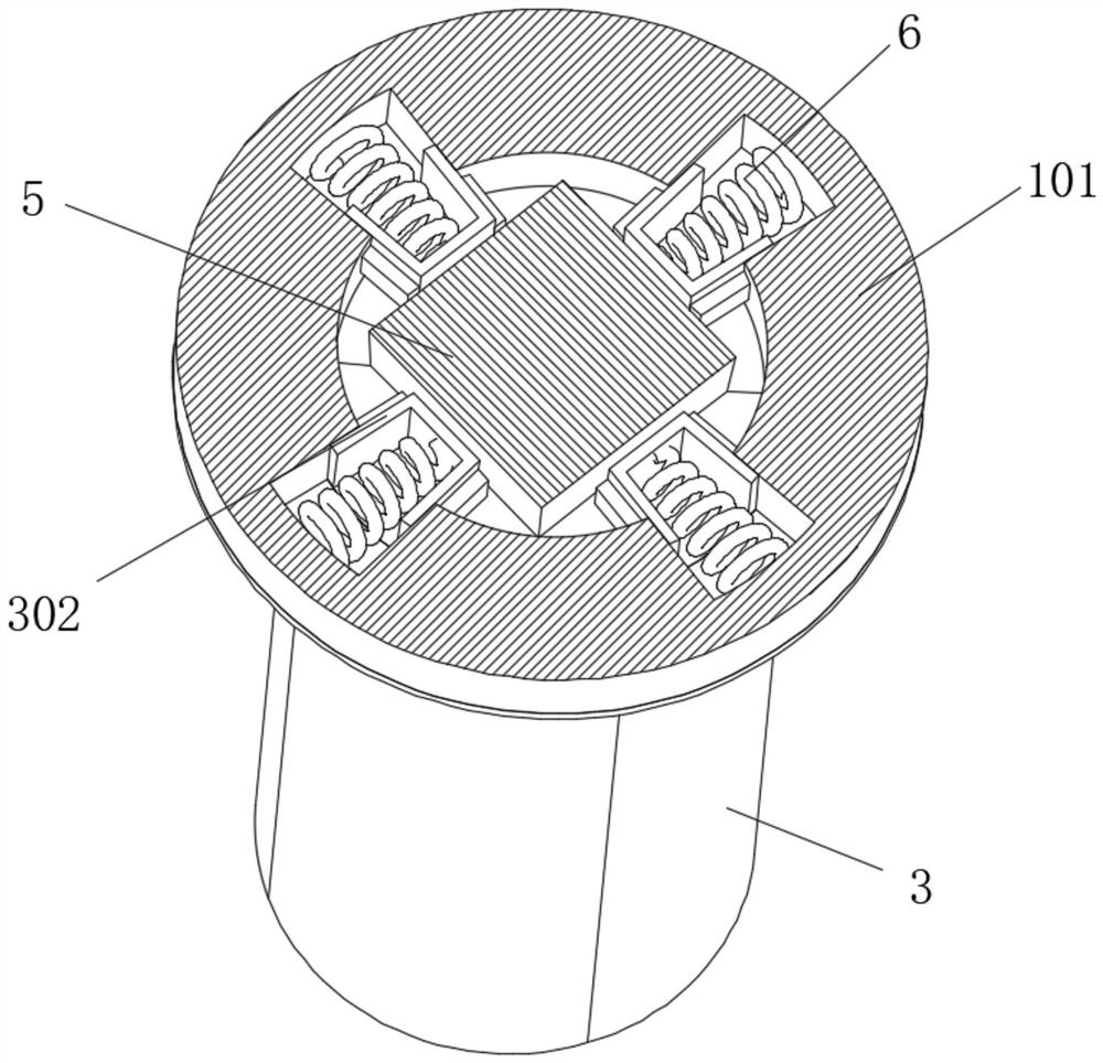
[0025] see Figure 1-8 , an airborne splitting machine for hard stones, comprising a hydraulic cylinder 1 and a splitting gun 2, the bottom of the hydraulic cylinder 1 is movable to install the splitting gun 2, the hydraulic cylinder 1 includes a cylinder body 101, and the top of the cylinder body 101 is provided with Oil inlet 102, from which hydraulic oil enters to provide power for the splitting gun. The inner ring of the cylinder body 101 is fixedly instal...


PUM


Abstract

The invention relates to the technical field of splitting machines and discloses an airborne type hard stone splitting machine. The airborne type hard stone splitting machine comprises a hydraulic cylinder and a splitting gun. The splitting gun is movably mounted at the bottom of the hydraulic cylinder. The hydraulic cylinder comprises a cylinder body. A plunger push rod is movably mounted on theportion, located at the top of a limiting ring, of an inner ring of the cylinder body. The inner ring of the bottom of the cylinder body is movably sleeved with the splitting gun. The splitting gun comprises four same splitting blocks. Each splitting block comprises a block body. The surface of the inner side of each block body is an inclined face. A block blocking block is movably mounted on oneside of each block body. A magnet is fixedly mounted in the middle of the inner side of each stone blocking block. An arc surface groove matched with the corresponding stone blocking block in shape and size is formed in the other side of each block body. A magnet groove matched with the corresponding magnet in shape and size is formed in the outer surface of each arc surface groove. According to the splitting machine, the whole round type splitting gun is formed by the four splitting blocks, the stone blocking blocks and the magnets are arranged on the outer sides of the splitting blocks, theuniform periphery splitting effect is achieved, and the service life is prolonged.

Description

technical field [0001] The invention relates to the technical field of splitters, in particular to an airborne splitter for hard stones. Background technique [0002] In rock mining or building construction, it is often necessary to break hard stones into small stones for processing. The equipment used in this process mostly uses splitters, because multiple splitters work at the same time, and It is also very heavy, so most of them are airborne. The splitting machine has a small risk factor and is safe and environmentally friendly. The existing splitting machine is composed of a wedge and two splitting blocks, and the wedge is pushed down by hydraulic pressure. Squeeze the splitting block to both sides, and the splitting block acts on the stone to both sides under the action of force to split the whole stone to produce cracks, but there are still some problems with the splitting machine: [0003] 1. Before splitting, the existing splitting machine needs to adjust the positi...

Claims


Application Information

Patent Timeline
Patent Type & Authority Patents(China)
IPC IPC(8): E21C37/02B28D7/00B28D1/22
CPCB28D1/222B28D7/00E21C37/02
Inventor 黄文忠
Owner 徐州天顾科技有限公司
Learn More