Coal mine roadway anchor cable supporting system
A technology for anchor cable support and coal mine roadway, which is applied in mining equipment, installation of bolts, earthwork drilling and mining, etc. It can solve the problems of poor yielding effect of the yielding tray, so as to improve the yielding capacity and reduce the degree of stress concentration , the effect of improving stability
- Summary
- Abstract
- Description
- Claims
- Application Information
AI Technical Summary
Problems solved by technology
Method used
Image

Examples
Embodiment Construction
[0030] In order to make the above objects, features and advantages of the present invention more comprehensible, specific embodiments of the present invention will be described in detail below in conjunction with the accompanying drawings.
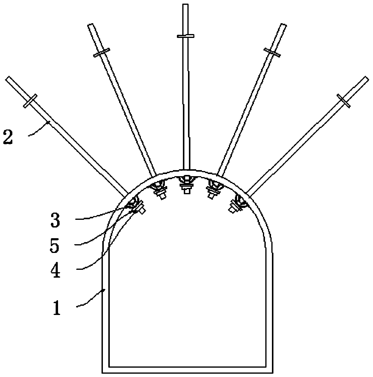
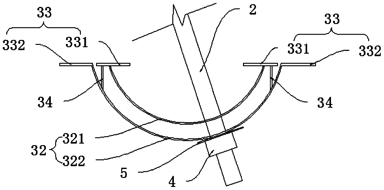
[0031] In order to solve the problem that the pressure yielding effect of the yielding tray is poor in the current anchor cable support system of coal mine roadway, the present invention provides a cable anchor support system for coal mine roadway, see figure 1 , figure 2 As shown, the coal mine roadway anchor cable support system includes a roadway 1, an anchor cable 2, a pressure relief tray 3 and an anchor 4; wherein, the pressure relief tray 3 is connected to the inner side of the roadway 1; the pressure relief tray 3 includes a circular arc-shaped The tray 32 and the bottom plate 33 of the raised structure, the tray 32 is fixedly connected with the bottom plate 33, and the bottom plate 33 is fixedly connected with the roadway 1; The...
PUM
 Abstract
Description
Claims
Application Information
PatSnap Eureka turns technology decisions into work you can execute. Powered by our Innovation Knowledge Graph, it runs expert workflows across engineering, life sciences, materials and intellectual property. Get your review-ready output in minutes.


