
A high-strength anchor

A high-strength, bolt-rod technology, used in bolt installation, mining equipment, earth-moving drilling, etc., can solve problems such as poor bolt strength, and achieve the effect of improving strength, good corrosion resistance, and convenient operation or disassembly

Inactive Publication Date: 2020-05-26
HULUNBUIR UNIV
View PDF13 Cites 0 Cited by
  • Summary
  • Abstract
  • Description
  • Claims
  • Application Information

AI Technical Summary

Problems solved by technology

[0003] However, the strength of the existing anchor rods is relatively poor, and those skilled in the art hope to provide a high-strength anchor rod that can effectively improve the strength

Method used


Image

  • A high-strength anchor
  • A high-strength anchor
  • A high-strength anchor

Examples


Embodiment 1

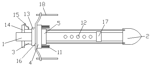
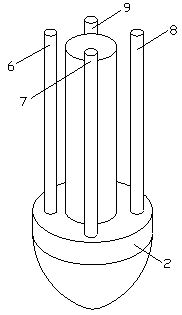
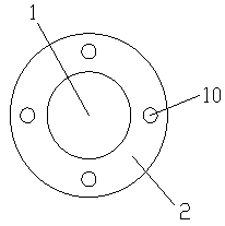
[0042] Such as Figure 1-3 As shown, a high-strength bolt includes a bolt body 1, a drill bit 2 is arranged on one end of the bolt body 1, and the drill bit 2 is fixedly connected with the bolt body 1. The other end is provided with a square nut 3, an arched backing plate 4 and a grout stopper 5 sequentially from left to right, the arched backing plate 4 and the grout stopper 5 are fixedly connected, and the arched backing plate 4 and the grout stopper The plugs 5 are all fixedly connected with the anchor body 1, the square nut 3 is threaded with the anchor body 1, and the arched backing plate 4 is provided with a first steel bar 6, a second steel bar 7, The third steel bar 8 and the fourth steel bar 9, the first steel bar 6, the second steel bar 7, the third steel bar 8 and the fourth steel bar 9 are arranged in a circular array, the first steel bar 6, the second steel bar 7, the The three steel bars 8 and the fourth steel bar 9 are all fixedly connected with the arched back...

Embodiment 2

[0049] Such as Figure 1-3 As shown, a high-strength bolt includes a bolt body 1, a drill bit 2 is arranged on one end of the bolt body 1, and the drill bit 2 is fixedly connected with the bolt body 1. The other end is provided with a square nut 3, an arched backing plate 4 and a grout stopper 5 sequentially from left to right, the arched backing plate 4 and the grout stopper 5 are fixedly connected, and the arched backing plate 4 and the grout stopper The plugs 5 are all fixedly connected with the anchor body 1, the square nut 3 is threaded with the anchor body 1, and the arched backing plate 4 is provided with a first steel bar 6, a second steel bar 7, The third steel bar 8 and the fourth steel bar 9, the first steel bar 6, the second steel bar 7, the third steel bar 8 and the fourth steel bar 9 are arranged in a circular array, the first steel bar 6, the second steel bar 7, the The three steel bars 8 and the fourth steel bar 9 are all fixedly connected with the arched back...


PUM


Abstract

The invention discloses a high-strength anchor rod. The high-strength anchor rod comprises an anchor rod body, wherein a drill bit is arranged on one end of the anchor rod body and is fixedly connected with the anchor rod body, a square nut, an arched cushion plate and a slurry blocking plug are sequentially arranged on the other end of the anchor rod body from left to right, the arched cushion plate is fixedly connected with the slurry blocking plug, the arched cushion plate and the slurry blocking plug are fixedly connected with the anchor rod body, and the square nut is connected with the anchor rod body through threads; and a first steel bar, a second steel bar, a third steel bar and a fourth steel bar which are used for reinforcing the anchor rod body are arranged on the arched cushion plate, are distributed in an annular array manner, are fixedly connected with the arched cushion plate and penetrate through the slurry blocking plug. According to the high-strength anchor rod, thestrength can be effectively improved.

Description

technical field [0001] The invention relates to a high-strength anchor rod. Background technique [0002] The bolt is the most basic part of roadway support in contemporary coal mines. It reinforces the surrounding rock of the roadway so that the surrounding rock can support itself. Now anchor rods are not only used in mines, but also in engineering technology for main body reinforcement of slopes, tunnels and dams. As a tensile member that goes deep into the ground, the bolt is connected to the engineering structure at one end, and the other end goes deep into the ground. The whole bolt is divided into a free section and an anchor section. area, whose function is to apply prestress to the anchor. [0003] However, the strength of existing anchor rods is poor, and those skilled in the art hope to provide a high-strength anchor rod that can effectively improve strength. Contents of the invention [0004] The technical problem to be solved by the present invention is to p...

Claims


Application Information

Patent Timeline
Patent Type & Authority Patents(China)
IPC IPC(8): E21D21/00E21D20/02C22C47/14C22C49/02C22C49/14C22C101/02
CPCC22C47/14C22C49/02C22C49/14E21D20/003E21D20/021E21D21/0006E21D21/0026
Inventor 郭文彬其他发明人请求不公开姓名
Owner HULUNBUIR UNIV
Features
  • Generate Ideas
  • Intellectual Property
  • Life Sciences
  • Materials
  • Tech Scout
  • Unparalleled Data Quality
  • Higher Quality Content
  • 60% Fewer Hallucinations
Learn More