High-precision adjusting device for calibration of linear displacement sensor
A kind of linear displacement sensor, technology of adjusting device
- Summary
- Abstract
- Description
- Claims
- Application Information
AI Technical Summary
Problems solved by technology
Method used
Image
Examples
Embodiment 1
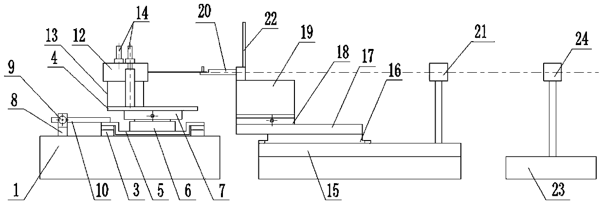
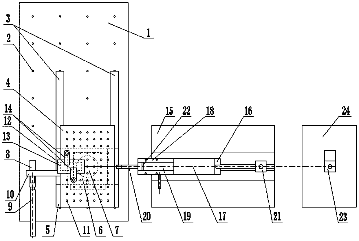
[0026] like figure 1 , figure 2 , a high-precision adjustment device for linear displacement sensor calibration, mainly used for calibrating different types and specifications of displacement sensors such as inductive displacement sensors, laser displacement sensors, resistive displacement sensors, and wire (rope) displacement sensors. Fixed adjustment of these displacement sensors. The device includes a sensor mounting part base 1 and a fixture mounting part moving table 15; the sensor mounting part base 1 is provided with two parallel first linear guide rails 3 and a fine-tuning screw 9, the two parallel first linear guides 3 A sliding base 5 is set on a linear guide 3, the fine adjustment screw 9 is connected to the end of the sliding base 5 close to the fine adjustment screw 9 through the transmission block 10, and the fine adjustment screw 9 controls the sliding base 5 through the transmission block 10 on the first linear guide 3. Displacement adjustment is made on th...
Embodiment 2
[0030] Example 2 Calibration and high-precision adjustment of a 1m-spec pull-type linear displacement sensor
[0031] First, the sensor connection measuring rod 20-2 of the calibration stay wire (rope) type displacement sensor is assembled on the support block 19; at the same time, the calibrated stay wire displacement sensor is placed on the sensor pad 13, and the two pressing parts 14 is vertically installed on the sensor fixing platform 4 through the second assembly fixing hole 11, and the pressing member 14 is pressed, and the pull-type linear displacement sensor placed on the sensor pad 13 is fixed between the sensor pad 13 and the pressing member 14.
[0032] Then the backguy of the backguy type line displacement sensor is connected with the sensor connection measuring rod 20-2 of the calibrated backguy (rope) type displacement sensor, and the coarse adjustment of the vertical direction and the horizontal direction is first carried out by the vertical adjustment mechanism...
Embodiment 3
[0033] Embodiment 3 Calibration and high-precision adjustment of laser displacement sensor
[0034] First of all, the sensor connection measuring rod 20-1 of the calibration laser displacement sensor or inductive displacement sensor is selected to be assembled on the support block 19, and the calibrated pull-type linear displacement sensor is placed on the sensor pad 13 at the same time, and the two The pressure piece 14 is vertically installed on the sensor fixing platform 4 through the second assembly fixing hole 11, the pressure piece 14 is pressed, and the laser displacement sensor placed on the sensor pad 13 is fixed between the sensor pad 13 and the pressure piece 14 .
[0035] The laser beam emitted by the laser displacement sensor hits the plane end of the sensor connected to the measuring rod 20-1 that is matched with the calibration laser displacement sensor or inductive displacement sensor, and the vertical adjustment mechanism 6 and the plane rotation adjustment me...
PUM
 Abstract
Description
Claims
Application Information
 - R&D
- Intellectual Property
- Life Sciences
- Materials
- Tech Scout
- Unparalleled Data Quality
- Higher Quality Content
- 60% Fewer Hallucinations
Browse by: Latest US Patents, China's latest patents, Technical Efficacy Thesaurus, Application Domain, Technology Topic, Popular Technical Reports.
© 2025 PatSnap. All rights reserved.Legal|Privacy policy|Modern Slavery Act Transparency Statement|Sitemap|About US| Contact US: help@patsnap.com


