Steel wire rope driving mechanism for optical inspection outside material cabin and exposure platform

A technology of driving mechanism and steel wire rope, which is applied in the direction of analyzing materials, analyzing materials through optical means, scientific instruments, etc. It can solve the problems that the driving mechanism cannot adapt to the space environment, and the safety and reliability cannot meet the space station, so as to save uplink resources , Satisfy the effect of safety and reliability, high reliability

Active Publication Date: 2020-05-08
TECH & ENG CENT FOR SPACE UTILIZATION CHINESE ACAD OF SCI
View PDF9 Cites 4 Cited by
  • Summary
  • Abstract
  • Description
  • Claims
  • Application Information

AI Technical Summary

Problems solved by technology

[0025] The technical problem to be solved by the present invention is that there is currently no relevant drive mechanism for optical inspection of materials outside the cabin, and the general drive mechanism cannot adapt to the space environment, and the safety and reliability cannot meet the requirements of the space station.

Method used


Image

  • Steel wire rope driving mechanism for optical inspection outside material cabin and exposure platform
  • Steel wire rope driving mechanism for optical inspection outside material cabin and exposure platform
  • Steel wire rope driving mechanism for optical inspection outside material cabin and exposure platform

Examples


Embodiment 1

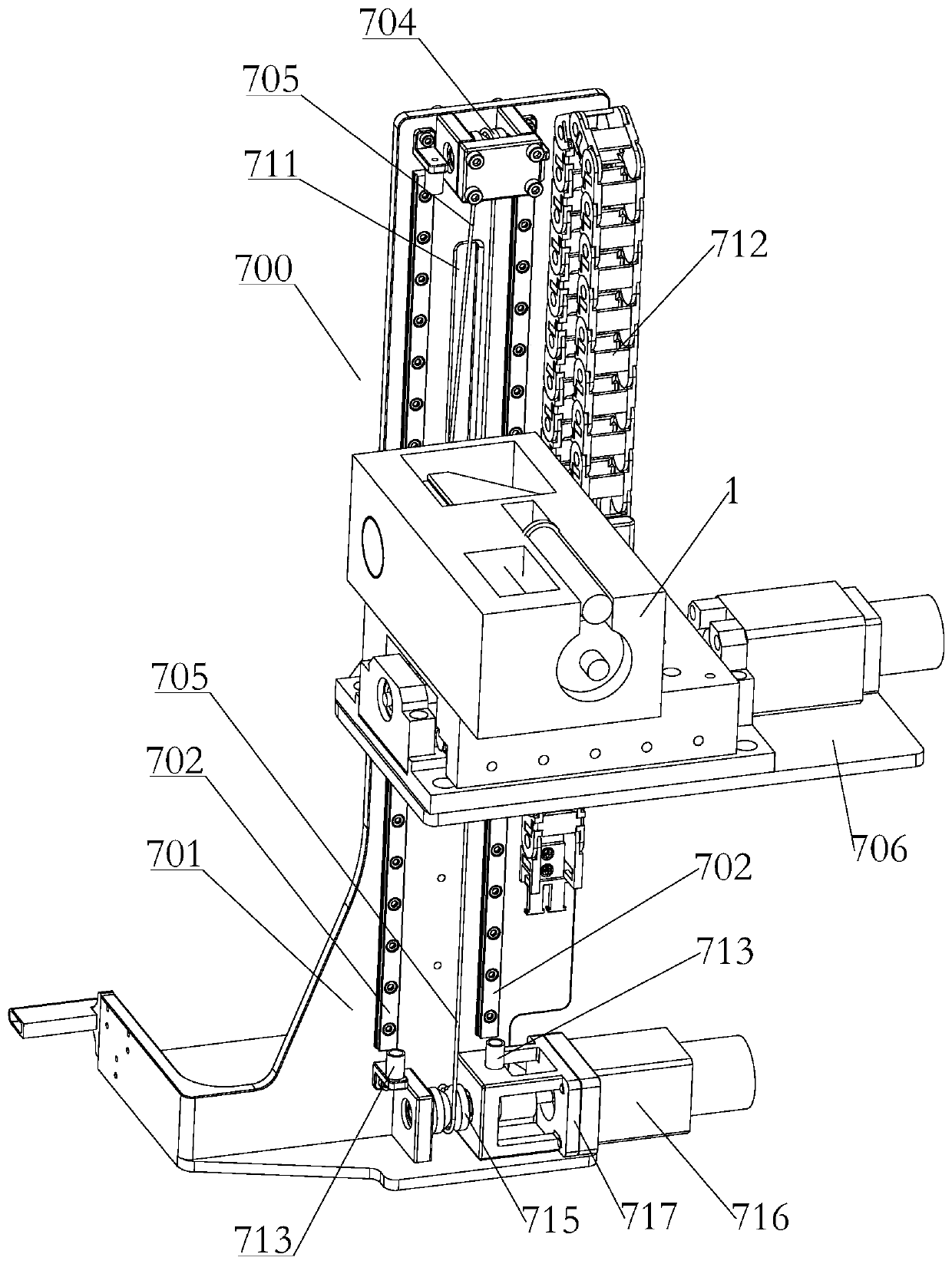
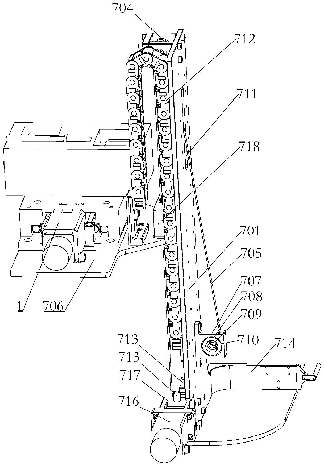
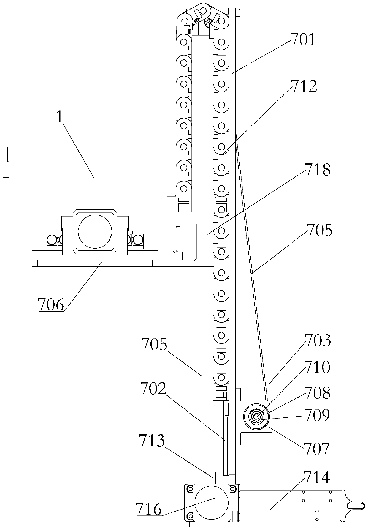
[0063] Such as Figure 1-Figure 4 As shown, a wire rope driving mechanism 700 for optical inspection of materials outside the cabin in this embodiment includes:

[0064] Bracket 701;

[0065] The guide rail 702 is installed on one side of the bracket 701, and is used for bearing and guiding the wire rope driving mechanism, supporting the reciprocating linear motion of the slider and the inspection mechanism;

[0066] The wire rope tightening device 703 is installed on the other side of the bracket 701, and moves along with the active wire rope winding wheel 715 to wind or release the wire rope 705 to ensure that the length of the wire rope 705 is normal and always in a pre-tightened state, so as to avoid transmission failure of the wire rope 705;

[0067] The driving device 716 is installed on the bottom of one side of the support 701, and its driving end is connected with an active wire rope winding wheel 715; the driving device 716 can use a motor as a power source to reali...

Embodiment 2

[0088]A material outdoor exposure platform in this embodiment includes a test box, an optical inspection module 1, an installation platform, and the wire rope drive mechanism 700, the test box is installed on the installation platform, and the test box The exposed surface after opening is arranged towards the surroundings of the installation platform, and the bottom of the bracket 701 is provided with a connecting plate 714 arranged vertically thereto, and the connecting plate 714 is installed on the peripheral side of the installation platform, and the optical inspection module 1 is installed on the bearing plate 706, and is driven by the wire rope 705 to reciprocate in a direction perpendicular to the installation platform, so as to inspect the exposed surface.

[0089] Wherein, the installation platform is square, the connecting plate 714 is installed on one side of the installation platform, and the bearing plate 706 is driven by the wire rope 706 to move in a direction per...


PUM


Abstract

The invention relates to a steel wire rope driving mechanism for optical inspection outside a material cabin and an exposure platform. The steel wire rope driving mechanism comprises a support; a guide rail, mounted on one side of the support; a steel wire rope tightening device, mounted on the other side of the support; a driving device, installed at the bottom of one side of the support, and thedriving end of the driving device being connected with a driving steel wire rope winding wheel; a steel wire rope idle wheel, mounted at the top of one side of the support; a steel wire rope, one endof the steel wire rope being connected to the driving steel wire rope winding wheel, and the other end of the steel wire rope being connected to the steel wire rope tightening device after being wound around the steel wire rope idle wheel; and a bearing plate used for mounting an optical inspection module, mounted on the guide rail in a sliding manner and connected to the steel wire rope. The invention provides a moving mechanism adapting to the space environment, the weight is reduced to the maximum extent, and the size is reduced. Meanwhile, the moving mechanism is convenient to install andoperate on the ground, reliability is high, the failure rate is small, uplink resources can be saved, and cost is saved.

Description

technical field [0001] The invention relates to the field related to the exposure of aerospace materials, in particular to a wire rope drive mechanism and an exposure platform for optical inspection of materials outside the cabin. Background technique [0002] In space science research, it is inseparable from the use of various materials, especially new materials. The purpose of material space environment exposure experiment is to study the service behavior of materials under the action of special space effects. [0003] Therefore, in the material cabin exposure experiment, how to realize a material cabin that can provide conditions for the on-orbit exposure of materials, provide conditions for the on-orbit movement of the optical imaging inspection module, and realize on-orbit detection in a special and complex space The external exposure platform is an important problem that needs to be solved urgently. [0004] Moreover, the movement mechanism applied to the space envir...

Claims


Application Information

Patent Timeline
Patent Type & Authority Applications(China)
IPC IPC(8): G01N21/84G01N17/00
CPCG01N21/84G01N17/00G01N2021/8411
Inventor 张伟贵张聚乐王乐天王珂杨鹏邓明哲郭志奇
Owner TECH & ENG CENT FOR SPACE UTILIZATION CHINESE ACAD OF SCI
Why Eureka
Try Eureka