
Method for finely complementing defect optical flow graph and application thereof

An optical flow graph and fine technology, applied in the field of image processing and deep learning, can solve the problems of optical flow graph defects, slow processing speed, and large amount of processed data, so as to improve operating efficiency, improve stability, and reduce data processing volume effect

Inactive Publication Date: 2020-05-08
SHANGHAI UNIV OF ENG SCI +2
View PDF6 Cites 1 Cited by
  • Summary
  • Abstract
  • Description
  • Claims
  • Application Information

AI Technical Summary

Problems solved by technology

[0005] The purpose of the present invention is to overcome the defects of poor completion effect, large amount of processed data and slow processing speed in the prior art, and to provide a method for finely complementing the defective optical flow map with good completion effect and fast processing speed. The present invention solves the defect problem of the optical flow diagram caused by the occlusion of the current flowing object, thereby greatly improving the integrity of the optical flow diagram and providing a reliable basis for subsequent processing. Complete

Method used


Image

  • Method for finely complementing defect optical flow graph and application thereof
  • Method for finely complementing defect optical flow graph and application thereof
  • Method for finely complementing defect optical flow graph and application thereof

Examples


Embodiment 1

[0081] A method for finely complementing a defect optical flow map, the steps of which are as follows Figure 4 As shown, specifically:

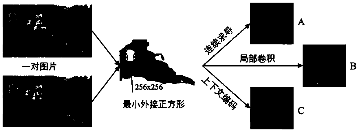
[0082] (1) Collect the smoke picture I in real time, process the smoke picture I to obtain the optical flow image, detect and locate the dynamic occlusion area of ​​the smoke, specifically:

[0083] (1.1) After real-time collection of smoke picture I, it is preprocessed. Preprocessing refers to the construction of smoke information data with label information to mark out the smoke area in smoke picture I, wherein the picture resolution of smoke picture I is greater than or equal to 1920 ×1080 pixels;

[0084] (1.2) Taking the preprocessed smoke picture I as input, input the trained LiteFlowNet to obtain the optical flow image of the smoke picture I, wherein, the input of LiteFlowNet is two adjacent frames in the preprocessed smoke picture I, and the output is Optical flow images corresponding to two adjacent frames;

[0085] LiteFlowNet h...

Embodiment 2

[0126] an electronic device such as Figure 5 As shown, including one or more processors, one or more memories, one or more programs and image acquisition devices;

[0127] The image acquisition device is used to collect the smoke picture I in real time, and one or more programs are stored in the memory, and when the one or more programs are executed by the processor, the electronic device performs the same kind of defect detection as in embodiment 1. A method for finely completing optical flow graphs.

[0128] It has been verified that the electronic device of the present invention has a simple structure and low cost, can finely complement a defect optical flow map, and has a good application prospect.


PUM


Abstract

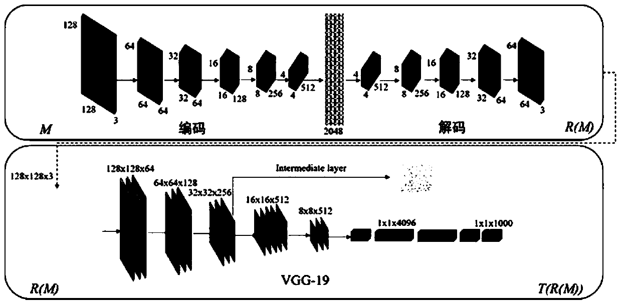
The invention discloses a method for finely complementing a defect optical flow graph and application thereof. The method comprises the following steps: acquiring a smoke picture I in real time, processing the smoke picture I to obtain an optical flow image, and positioning a smoke dynamic shielding area; extracting an image region from the center of the minimum bounding square of the dynamic occlusion region; inputting the image region into a trained improved GAN network to obtain a replacement image of the dynamic occlusion region, wherein the improved GAN network refers to replacing confrontation loss in a loss function of a context network module of the GAN network with WGAN loss in a loss function of a context network module of the improved GAN network; processing the replacement image of the dynamic occlusion area through a VGG-19 network, and adding texture information; and mapping the image obtained by adding the texture information to an optical flow image to obtain a completeglobal optical flow graph. The method disclosed by the invention is good in completion effect and high in processing speed; the electronic equipment is simple in structure, low in cost and good in application prospect.

Description

technical field [0001] The invention belongs to the technical field of image processing and deep learning, and relates to a method for finely complementing a defective optical flow map and an application thereof. Background technique [0002] With the continuous development of machine vision and image processing, the effect of visual inspection must become more and more accurate, and the technology of image processing needs to be broken through one by one. Occlusion is a common interference in vision. When detecting moving objects in the field of view via optical flow, there are various things that can cause occlusions, including other objects. Occlusion means that part of the object is covered and part of the object is lost. The vision system obviously cannot detect things that are not present in the image, affecting the robustness of moving object detection. Taking the detection of smoke concentration as an example, the accurate evaluation of smoke concentration largely ...

Claims


Application Information

Patent Timeline
IPC IPC(8): G06T5/00G06T7/40G06T11/00G06N3/04G06K9/20
CPCG06T7/40G06T11/001G06V10/22G06N3/045G06T5/00G06T5/70
Inventor 张伟伟郭鹏宇李传昌陈超邱永锋陈彦召赵建波
Owner SHANGHAI UNIV OF ENG SCI
Learn More