
Audio data encoding method and device, audio data decoding method and device, electronic equipment and storage medium

An audio data and audio coding technology, applied in the Internet field, can solve the problems of poor real-time audio transmission quality and achieve the effect of improving the success rate

Active Publication Date: 2020-05-08
BEIJING DAJIA INTERNET INFORMATION TECH CO LTD
View PDF6 Cites 4 Cited by
  • Summary
  • Abstract
  • Description
  • Claims
  • Application Information

AI Technical Summary

Problems solved by technology

[0005] The present disclosure provides an audio data encoding and decoding method, device, electronic equipment, and storage medium to at least solve the problem of poor real-time audio transmission quality in related audio recovery technologies

Method used


Image

  • Audio data encoding method and device, audio data decoding method and device, electronic equipment and storage medium
  • Audio data encoding method and device, audio data decoding method and device, electronic equipment and storage medium
  • Audio data encoding method and device, audio data decoding method and device, electronic equipment and storage medium

Examples


example 1

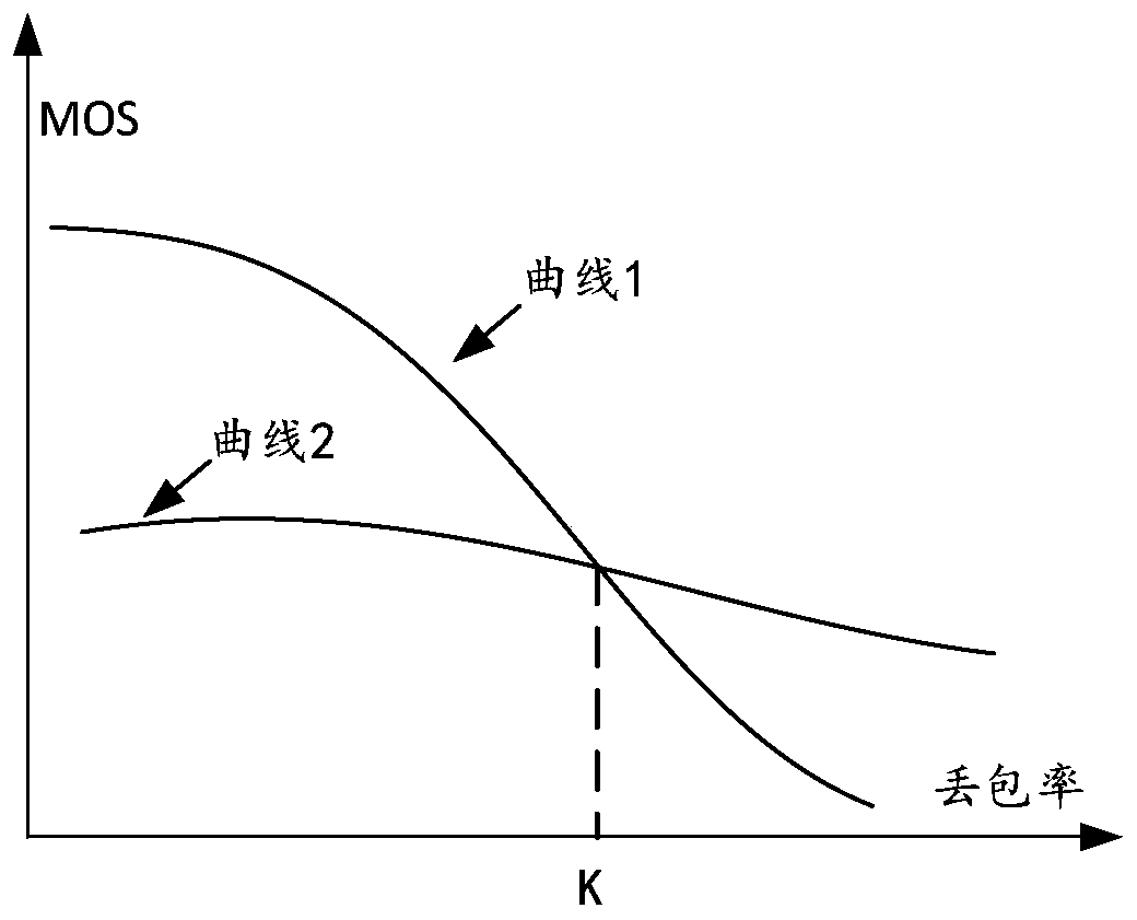
[0100] Example 1, such as image 3 As shown, in different encoding modes, by using the PESQ software tool, calculate the MOS of audio data at different packet loss rates. Depend on image 3 It can be seen that under different packet loss rates, audio data corresponds to different MOSs, and the corresponding relationship between different packet loss rates and MOSs in the first encoding mode is formed as follows image 3 In the curve 1, the corresponding relationship between different packet loss rates and MOS in the second coding mode is formed as image 3 Curve 2 in , where the packet loss rate value corresponding to the intersection of curve 1 and curve 2 (such as image 3 K) in is the critical threshold (ie, the preset threshold).

[0101] In this way, according to the relationship between the packet loss rate and the preset threshold, the sending end selects a coding mode suitable for the current actual network environment to encode the subsequent audio data. During the...

example 2

[0151]In Example 2, take the receiving end receiving the data packet of the first audio data sent by the sending end as an example. Within a certain period of time, the number of data packets of the first audio data sent by the sending end is S, and the number of data packets of the first audio data actually received by the receiving end is R, so the packet loss rate is (S-R) / S. The receiving end can feed back the calculated packet loss rate result to the sending end through the server.

[0152] Exemplarily, when the sending end sends a data packet of a piece of data, it will write a data packet serial number for each data packet of this audio data, and after receiving the data packet, the receiving end queries the last data packet serial number and the first The number of serial numbers between the serial numbers of data packets can be used to calculate the number of data packets sent by the sender. By querying the number of missing serial numbers between the last data packet...


PUM


Abstract

The invention relates to an audio data encoding method and device, an audio data decoding method and device, electronic equipment and a storage medium, and aims to at least solve the problem of poor real-time audio transmission quality in related audio recovery technologies. The audio data encoding method comprises the following steps: obtaining a packet loss rate of sent first audio data, the packet loss rate being a ratio of a packet loss number to a first number, the packet loss number being a difference between a second number and the first number, the first number being the number of datapackets of the first audio data sent by a sending end, and the second number being the number of data packets of the first audio data received by a receiving end; determining an encoding mode of second audio data to be transmitted according to the packet loss rate; and encoding the second audio data by adopting the encoding mode. The audio data encoding method and device, the audio data decodingmethod and device, the electronic equipment and the storage medium are applied to an audio transmission scene.

Description

technical field [0001] The present disclosure relates to the technical field of the Internet, and in particular to audio data encoding and decoding methods, devices, electronic equipment and storage media. Background technique [0002] At present, the use of the Internet for real-time audio transmission is becoming more and more common. In the process of real-time audio transmission, affected by network factors, there may be packet loss during the transmission process, resulting in a decrease in the quality of the audio signal received by the receiving end. [0003] In related technologies, in order to improve the quality of the audio signal received by the receiving end, the receiving end can use audio packet loss recovery technology (for example, forward error correction (Forward Error Correction, FEC) technology) to recover the lost audio data packets . Specifically, when sending an audio data packet (hereinafter referred to as audio data packet A), the sending end may c...

Claims


Application Information

Patent Timeline
IPC IPC(8): G10L19/005
CPCG10L19/005
Inventor 邢文浩张晨
Owner BEIJING DAJIA INTERNET INFORMATION TECH CO LTD
Learn More