Supercharge Your Innovation With Domain-Expert AI Agents!

Integrated line optical fiber differential protection system

A differential protection, integrated technology, applied in the field of power grid, can solve problems such as high engineering cost, short line length, and large number of optical fiber communication channels.

Inactive Publication Date: 2020-05-08
CHINA ENERGY ENG GRP GUANGDONG ELECTRIC POWER DESIGN INST CO LTD
View PDF3 Cites 0 Cited by
  • Summary
  • Abstract
  • Description
  • Claims
  • Application Information

AI Technical Summary

Problems solved by technology

However, the medium and low voltage distribution network has the characteristics of complex and changeable line connection methods, short line length, common three-terminal and more than three-terminal T-connection lines, and fewer inter-station optical fiber communication channels. figure 1 (T1, T2, and T3 in the figure are all current collectors, and CB1, CB2, and CB3 are all circuit breakers). For the network topology of multi-terminal T-connection, the number of line protection devices and optical fiber communication channels is large, such as figure 1 The medium switch station needs to be equipped with 3 differential protection devices, and 3 optical fiber channels are required between the switch station, step-down converter station 01 and converter station 03, so there are many protection devices and fiber optic communication channels in the entire line. The total cost of the project is high

Method used


Image

  • Integrated line optical fiber differential protection system
  • Integrated line optical fiber differential protection system
  • Integrated line optical fiber differential protection system

Examples


Embodiment Construction

[0032] The following will clearly and completely describe the technical solutions in the embodiments of the present invention with reference to the accompanying drawings in the embodiments of the present invention. Obviously, the described embodiments are only some, not all, embodiments of the present invention. Based on the embodiments of the present invention, all other embodiments obtained by persons of ordinary skill in the art without creative efforts fall within the protection scope of the present invention.

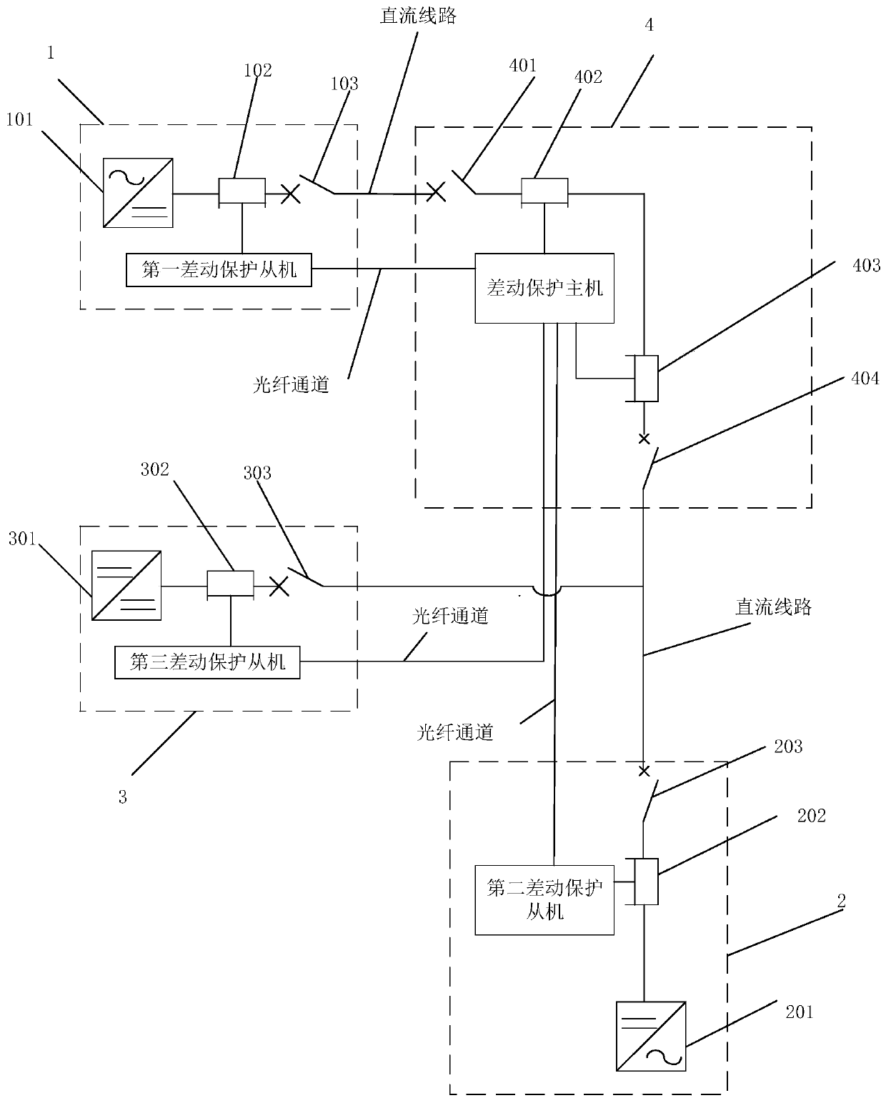
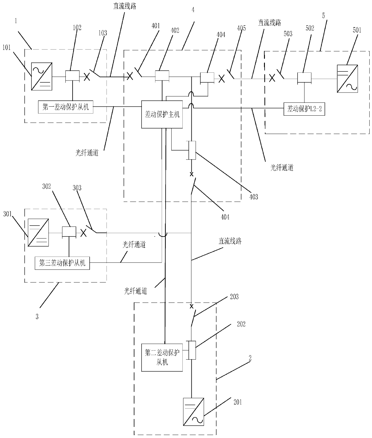
[0033] Such as figure 2 As shown, it is an integrated line optical fiber differential protection system provided by an embodiment of the present invention, which is suitable for medium and low voltage DC distribution networks, including: the first converter station subsystem 1 and the second converter station subsystem 2 , switch station subsystem 4 and step-down converter station subsystem 3;

[0034] The first converter station subsystem includes a first differ...


PUM


Abstract

The invention discloses an integrated line optical fiber differential protection system. The system comprises a first converter station subsystem, a second converter station subsystem, a switching station subsystem and a buck converter station subsystem. The first converter station subsystem comprises a first differential protection slave; the second converter station subsystem comprises a seconddifferential protection slave; the buck converter station subsystem comprises a third differential protection slave; the switching station subsystem comprises a differential protection host; each differential protection slave is used for collecting current information of the corresponding subsystem and sending the current information to the differential protection host; and the differential protection host is used for carrying out line differential protection action calculation on each subsystem according to the current information of each subsystem, and sending a tripping command to the corresponding differential protection slave when a calculation result conforms to a preset tripping condition, so that the differential protection slave controls the corresponding subsystem to execute a tripping action after receiving the tripping command. By implementing the embodiment of the invention, the engineering cost of the optical fiber differential protection system of the medium-low-voltagedirect-current power distribution network can be reduced.

Description

technical field [0001] The invention relates to the technical field of power grids, in particular to an integrated optical fiber differential protection system for lines. Background technique [0002] The DC distribution network refers to the DC power network that receives electric energy from the power source side (transmission network, power generation equipment, distributed power supply, etc.) and distributes it to various users locally or step by step through DC power distribution facilities. Among them, the DC distribution network of ±1.5kV~±50kV is the medium-voltage DC distribution network, and the DC distribution network of ±110V~±750V is the low-voltage DC distribution network; [0003] Line optical fiber differential protection refers to the line protection that uses split-phase current differential elements as fast main protection and uses multiplexed or dedicated optical fibers as channels. The point-to-point transmission method is adopted for the high-voltage D...

Claims


Application Information

Patent Timeline
IPC IPC(8): H02H7/26H02H7/28
CPCH02H7/262H02H7/268H02H7/28
Inventor 张浩陈建福鲁丽娟周钰刘仁亮施世鸿伦振坚彭冠炎钟强杨锐雄
Owner CHINA ENERGY ENG GRP GUANGDONG ELECTRIC POWER DESIGN INST CO LTD
Features
  • R&D
  • Intellectual Property
  • Life Sciences
  • Materials
  • Tech Scout
  • Unparalleled Data Quality
  • Higher Quality Content
  • 60% Fewer Hallucinations
Learn More