Flying fork type winding machine and working method thereof

A technology of winding machine and winding mechanism, which is used in electromechanical devices, manufacturing motor generators, electrical components, etc., can solve the problems of large wear and tear of enameled wires, affecting product quality, and damage to enameled wires, so as to improve the accuracy of wiring and winding. The effect of speed, improving product quality and improving production efficiency

Pending Publication Date: 2020-05-08
FUJIAN UNIV OF TECH
View PDF0 Cites 4 Cited by
  • Summary
  • Abstract
  • Description
  • Claims
  • Application Information

AI Technical Summary

Problems solved by technology

[0002] With the continuous advancement of science and technology, there are many types of winding machine equipment, such as stator winding machines, electromagnetic switch coil winding machines, etc. Among them, there are two main types of stator winding machines. One is that the guide pin drives the enameled wire to move up and down at the same time. It can move back and forth, allowing the stator core to cooperate with the guide needle to complete the winding. The other is the flying fork stator core winding machine, but there are two problems with the current flying fork winding machine, one is the accuracy of the coil arrangement Insufficient, the other is the damage to the enameled wire
[0003] When the flying fork winding machine is winding, the flying fork rotates at high speed to wind the enameled wire on the stator core. Because the flying fork is too fast to swing the enameled wire, it will cause collision between the enameled wire and the stator core, resulting in deformation of the enameled wire and even paint stripping. , affecting product quality; at the same time, when the stator core is wound, the enameled wire and the flying fork are the wear and tear of the enameled wire due to the sliding friction force. In severe cases, the enameled wire will be thinned, making the resistance larger

Method used


Image

  • Flying fork type winding machine and working method thereof
  • Flying fork type winding machine and working method thereof
  • Flying fork type winding machine and working method thereof

Examples


Embodiment Construction

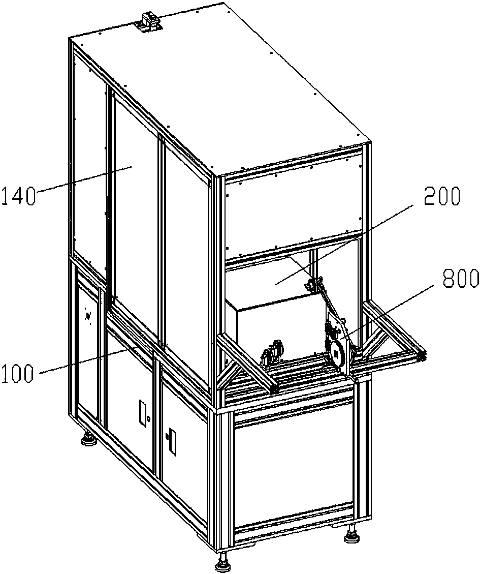
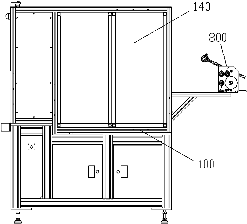
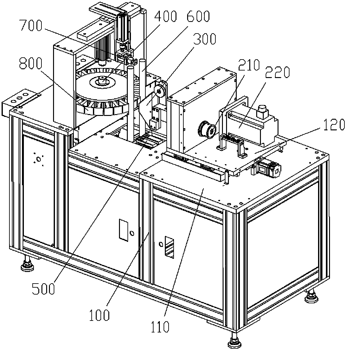
[0030] Such as Figure 1~10 As shown, a flying fork type winding machine includes a body 100 with a table 110, a headstock 200 capable of moving back and forth is installed on the table 110 of the body 100, and a center with a threading hole is installed in the headstock 200 The main shaft 210, the front end of the main shaft is equipped with a winding mechanism 300 for winding, and the table 110 of the body 100 is also equipped with an installation mechanism 400 located in front of the winding mechanism 300 for installing the stator core. The winding mechanism 300 includes a flying fork 310 installed at the front end of the main shaft and a trapezoidal wire slider 320 with a small front and a large rear for forcing the enameled wire to slide into the teeth of the stator core. The liftable positioning mechanism 500, the front of the winding mechanism 300 is provided with a pair of wire protection rods 600 used to block between the stator core and the winding mechanism to preve...


PUM


Abstract

The invention relates to a flying fork type winding machine and a working method thereof. The machine comprises a machine body, and a main shaft box capable of moving front and back is installed on the table board of the machine body. A main shaft with a threading hole in the center is mounted in the main shaft box; a winding mechanism for winding is mounted at the front end of the main shaft; a mounting mechanism which is positioned in front of the winding mechanism and is used for mounting a stator iron core is also mounted on the tabletop of the machine body; the winding mechanism comprisesa flying fork arranged at the front end of the main shaft and a trapezoidal wire sliding block which is used for forcing the enameled wire to slide into the tooth part of the stator iron core and hasa small front part and a large rear part; a liftable positioning mechanism used for guiding the wire sliding block to move back and forth is arranged below the wire sliding block, and a pair of wireprotection rods used for blocking between the stator iron core and the winding mechanism to prevent the enameled wire from touching the stator iron core is arranged in front of the winding mechanism.The flying fork type winding machine can effectively protect an enameled wire, avoids the problems of enameled wire deformation, paint removal and the like caused by collision between the enameled wire and the stator iron core in the winding process, and reduces coil damage.

Description

technical field [0001] The invention relates to a flying fork type winding machine and its working method. Background technique [0002] With the continuous advancement of science and technology, there are many types of winding machine equipment, such as stator winding machines, electromagnetic switch coil winding machines, etc. Among them, there are two main types of stator winding machines. One is that the guide pin drives the enameled wire to move up and down at the same time. It can move back and forth, allowing the stator core to cooperate with the guide needle to complete the winding. The other is the flying fork stator core winding machine, but there are two problems with the current flying fork winding machine, one is the accuracy of the coil arrangement Insufficient, the other is the damage to the enameled wire. [0003] When the flying fork winding machine is winding, the flying fork rotates at high speed to wind the enameled wire on the stator core. Because the f...

Claims


Application Information

Patent Timeline
Patent Type & Authority Applications(China)
IPC IPC(8): H02K15/085
CPCH02K15/085
Inventor 曾寿金周佳辉肖鹏程吴肇桢叶建华
Owner FUJIAN UNIV OF TECH
Why Eureka
Try Eureka