Low-delay adaptive bidirectional DCDC converter and control method thereof
A control method and converter technology, applied in control/regulation systems, output power conversion devices, DC power input conversion to DC power output, etc. problems, to achieve the effect of optimizing the overall design, shortening the work process, and improving the switching speed
- Summary
- Abstract
- Description
- Claims
- Application Information
AI Technical Summary
Problems solved by technology
Method used
Image
Examples
Embodiment 1
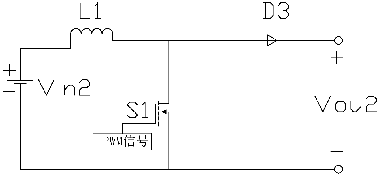
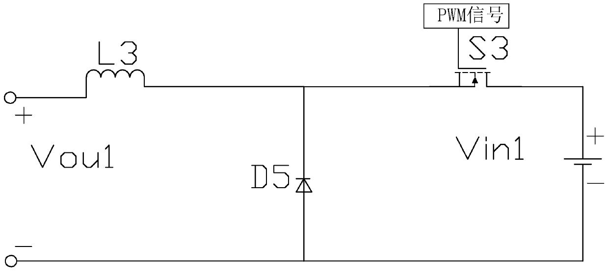
[0033] Embodiment 1: A low-delay adaptive bidirectional DCDC converter of this embodiment, such as figure 1 As shown, it includes a voltage source 1, a first DCDC conversion unit 2, a second DCDC conversion unit 3, a third DCDC conversion unit 4, a first external circuit 5 and a second external circuit 6, and the voltage source 1 is connected to the cathode of the diode D1 connected to one end of the second DCDC conversion unit 3, the anode of the diode D1 is connected to one end of the first DCDC conversion unit 2, the other end of the second DCDC conversion unit 3 is connected to the anode of the diode D2, and the first DCDC conversion unit The other end of 2, one is connected to the cathode of diode D2, the other is connected to the first external circuit 5, and the other is connected to one end of the third DCDC conversion unit 4, and the other end of the third DCDC conversion unit 4 is connected to the second external circuit 6, the voltage source 1 provides the driving v...
Embodiment 2
[0038] Embodiment 2: A low-delay adaptive bidirectional DCDC converter of this embodiment, such as Figure 4 As shown, the second DCDC conversion unit 3 is an isolated converter, including a converter primary side circuit and a converter secondary side circuit, the two are connected through a transformer T, and the converter secondary side circuit includes an inductor L2, a diode D4, The power switch tube S2, the resistor RL and the capacitor Cf, one end of the inductor L2 is connected to the positive pole of the diode D4, the series circuit of the inductor L2 and the diode D4 is connected in parallel with the series circuit of the inductor L1 and the diode D3, the negative pole of the diode D4 is connected to the output voltage Vou2 A capacitor Cf and a resistor RL are connected in parallel between the negative poles, a power switch tube S2 is connected between the negative pole of the diode D4 and the negative pole of the output voltage Vou2, the drain of the power switch tub...
PUM
 Abstract
Description
Claims
Application Information
 - R&D
- Intellectual Property
- Life Sciences
- Materials
- Tech Scout
- Unparalleled Data Quality
- Higher Quality Content
- 60% Fewer Hallucinations
Browse by: Latest US Patents, China's latest patents, Technical Efficacy Thesaurus, Application Domain, Technology Topic, Popular Technical Reports.
© 2025 PatSnap. All rights reserved.Legal|Privacy policy|Modern Slavery Act Transparency Statement|Sitemap|About US| Contact US: help@patsnap.com


