Power supply shell waterproof device

A technology of waterproof device and power supply shell, which is applied in the direction of electrical equipment casing/cabinet/drawer, closed casing, electrical components, etc., which can solve the problems of not achieving the sealing and waterproof effect, affecting the normal operation of electrical components, etc., and improving the safety of use Performance and service life, increase the contact position, improve the effect of sealing connection

Pending Publication Date: 2020-05-08
FOSHAN SHUNDE GUANYUDA POWER SUPPLY CO LTD
View PDF1 Cites 2 Cited by
  • Summary
  • Abstract
  • Description
  • Claims
  • Application Information

AI Technical Summary

Problems solved by technology

It is said that this structure not only retains the light transmission effect, but also absolutely guarantees the waterproof performance, solves the cracking problem of the plastic shell, prevents the box body from breaking at the root of the nut when the box vibrates and falls, and prolongs its service life; however, The upper and lower boxes of the above structure use the form of flat-pressed H-shaped sealing strips to achieve sealing and waterproofing, and the waterproof effect is effective, and the input line and output line of the power supply respectively use the split type of the incoming line sealing ring and the outgoing line sealing ring. Set for sealing and waterproofing, since the sealing strip, the sealing ring of the incoming line and the sealing ring of the outgoing line are set separately from each other, there will always be large or small gaps after assembly of each component, and the water vapor or moisture will be lost in the actual use process. The inside of the upper and lower boxes will be penetrated from these gaps, affecting the normal operation of the electrical components inside the upper and lower boxes, and the effective sealing and waterproof effect cannot be achieved.

Method used


Image

  • Power supply shell waterproof device
  • Power supply shell waterproof device
  • Power supply shell waterproof device

Examples


Embodiment Construction

[0020] The present invention will be further described below in conjunction with the accompanying drawings and embodiments.

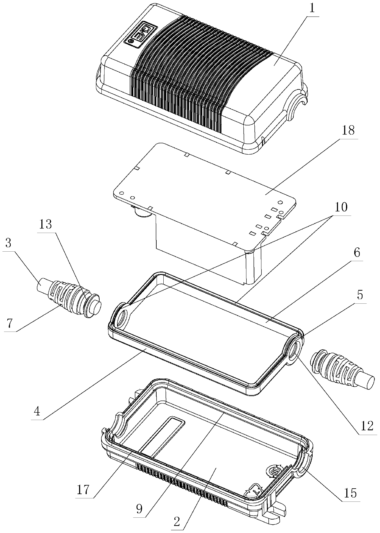
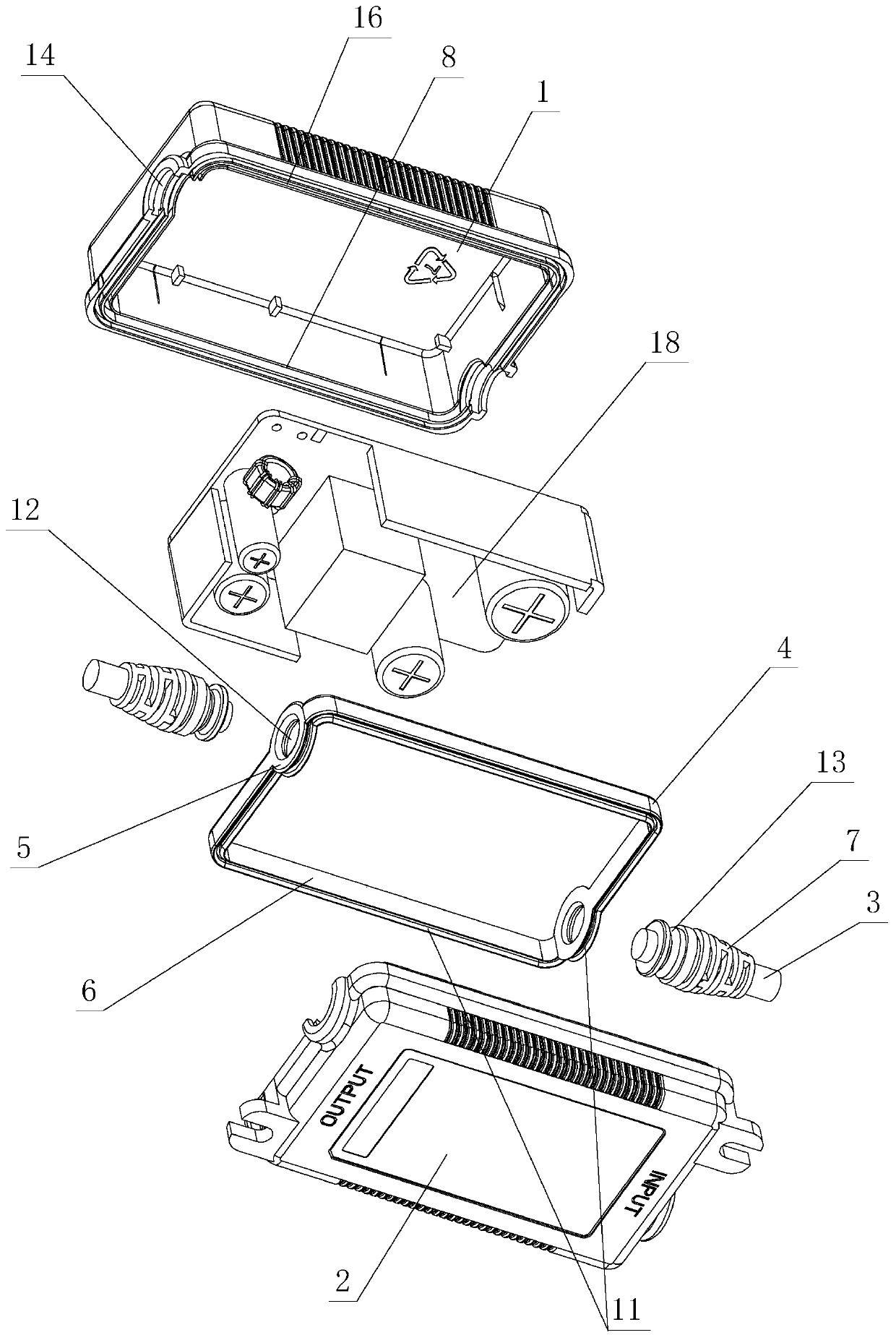
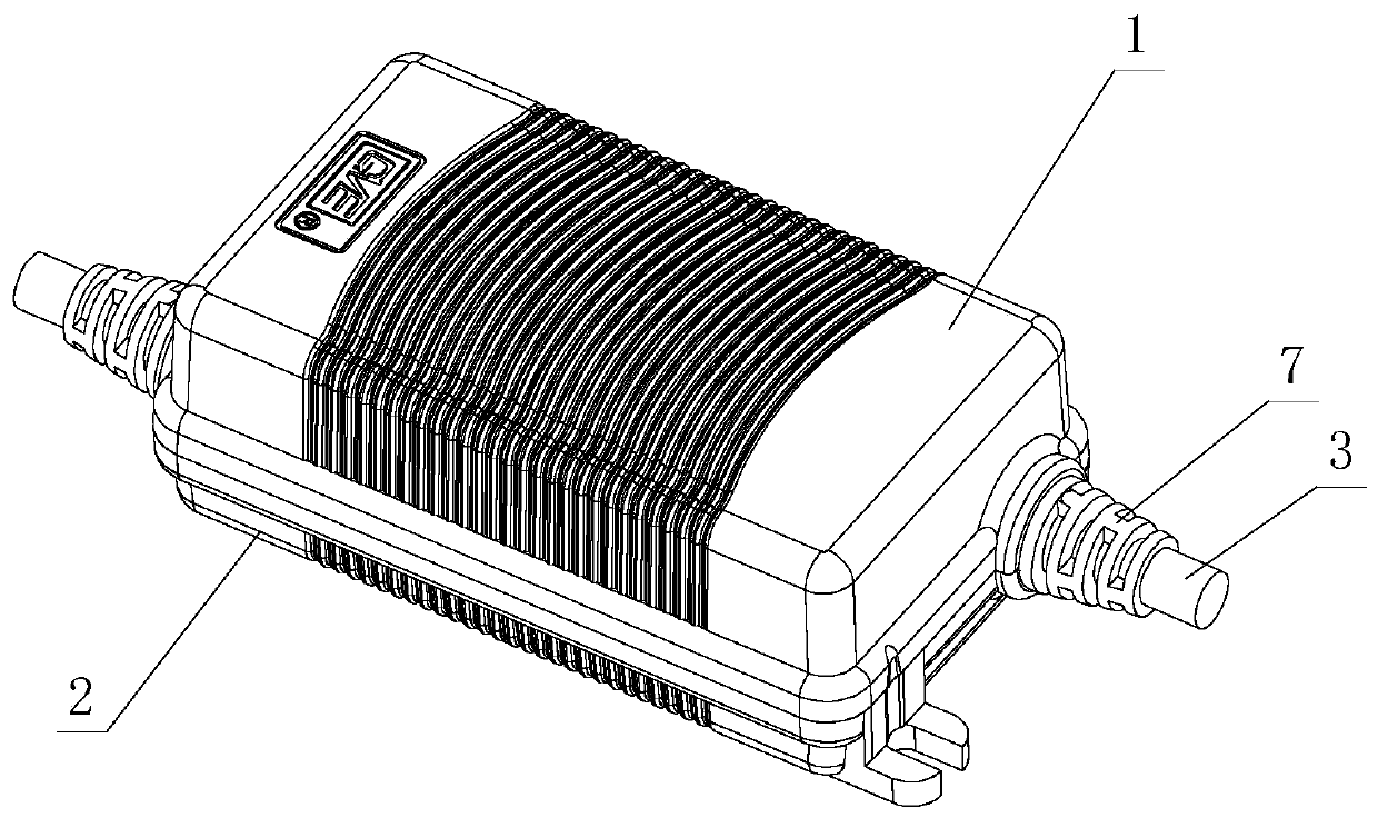
[0021] see Figure 1-Figure 7 , The waterproof device for the power supply case is mainly applicable to the switching power supply case and the power adapter case, which includes an upper case 1, a lower case 2, a power cord 3, and a waterproof part 4.

[0022] Such as figure 1 , figure 2 As shown, the waterproof member 4 is integrally formed by a material having certain elasticity or plastic, and includes a wire sealing position 5 and a casing position 6 connected end to end.

[0023] There are two power cords 3 , which correspond to the power input and output cords respectively. Therefore, there are also two cord sealing positions 5 corresponding to the power cords 3 , which are respectively located at the left and right ends of the enclosure position 6 . Specifically, the wire sealing position 5 is circular or elliptical, and the shell position 6...


PUM


Abstract

A power supply shell waterproof device comprises an upper shell, a lower shell, a power line and a waterproof part. The waterproof part is integrally formed by a wire sealing position and a shell sealing position which are connected end to end. The power line is provided with a joint and is arranged in the line sealing position through the joint in a sealing way, the upper shell is provided with an upper waterproof rib and is pressed above the line sealing position and the shell sealing position through the upper waterproof rib in the sealing way, and the lower shell is provided with a lower waterproof rib and is pressed below the line sealing position and the shell sealing position through the lower waterproof rib in the sealing way. In the invention, the structure is improved; contact positions among the upper shell, the lower shell, the joint and the waterproof part after assembly are increased to form more fitting surfaces; in addition, gaps formed after the upper shell, the lowershell, the joint and the waterproof part are assembled can be avoided so that water vapor or moisture is completely prevented from entering the upper shell and the lower shell, and waterproof performance of the power supply shell is greatly improved; and a maximum waterproof effect is achieved, use safety of the power supply shell is correspondingly improved, and a service life is correspondinglyprolonged.

Description

technical field [0001] The invention relates to a waterproof device for a power supply case. Background technique [0002] The Chinese patent document number is CN207466404U, which discloses a waterproof new energy vehicle charging control box on June 8, 2018. It includes an upper box body and a lower box body, and an incoming line seal is provided in a spiral sheath at one end of the upper and lower box bodies. There is an outgoing line sealing ring in the spiral sheath at the other end, multiple sets of locking screws are symmetrically arranged in the lower box body, and a conformal sealing strip is arranged between the upper box body and the lower box body. The cross section of the sealing strip is Type H. It is said that this structure not only retains the light transmission effect, but also absolutely guarantees the waterproof performance, solves the cracking problem of the plastic shell, prevents the box body from breaking at the root of the nut when the box vibrates ...

Claims


Application Information

Patent Timeline
Patent Type & Authority Applications(China)
IPC IPC(8): H05K5/02H05K5/06H05K5/00H05K7/14
CPCH05K5/0004H05K5/0217H05K5/0247H05K5/069H05K7/1427
Inventor 区智雄
Owner FOSHAN SHUNDE GUANYUDA POWER SUPPLY CO LTD
Why Eureka
Try Eureka