
Computer network line arranging device

A computer network and circuit technology, applied in cooling/ventilation/heating transformation, electrical components, electrical equipment structural parts, etc. The line is damaged and the effect of ensuring normal operation

Inactive Publication Date: 2020-05-08
KAIFENG UNIV
View PDF14 Cites 5 Cited by
  • Summary
  • Abstract
  • Description
  • Claims
  • Application Information

AI Technical Summary

Problems solved by technology

[0002] Computer network architecture can be described from three aspects: network architecture, network organization, and network configuration. Network organization describes computer networks from two aspects: network physical structure and network realization. Network configuration describes computer networks from network applications The layout of the network, hardware, software and communication lines to describe the computer network, the network architecture is to describe the structure of the computer network from the functional point of view, the computer network is composed of multiple interconnected nodes, and the nodes must constantly exchange data and control Information, in order to exchange data in an orderly manner, each node must abide by a set of reasonable and rigorous structured management system. The computer network is realized according to the highly structured design method and the principle of functional layering, that is, the computer network system The content of the structure, the existing computer network lines are often disorganized, there is no fixed placement device, the wiring is more troublesome, and the heat generated by the computer network center is relatively large, and the heat dissipation effect in the box is not good, which will affect its normal operation

Method used


Image

  • Computer network line arranging device
  • Computer network line arranging device
  • Computer network line arranging device

Examples


Embodiment Construction

[0019] The technical solutions of the present invention will be clearly and completely described below in conjunction with the embodiments. Apparently, the described embodiments are only some of the embodiments of the present invention, not all of them. Based on the embodiments of the present invention, all other embodiments obtained by persons of ordinary skill in the art without creative efforts fall within the protection scope of the present invention.

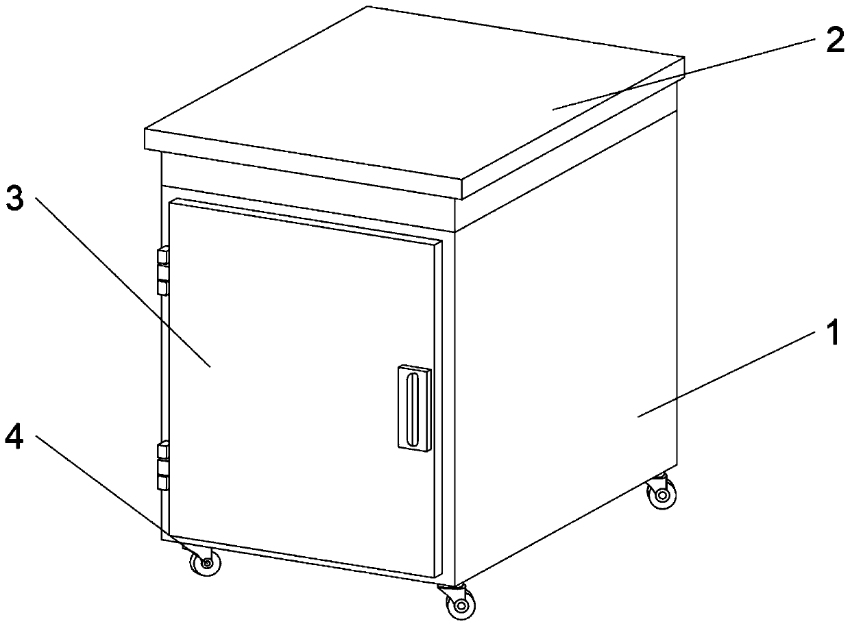
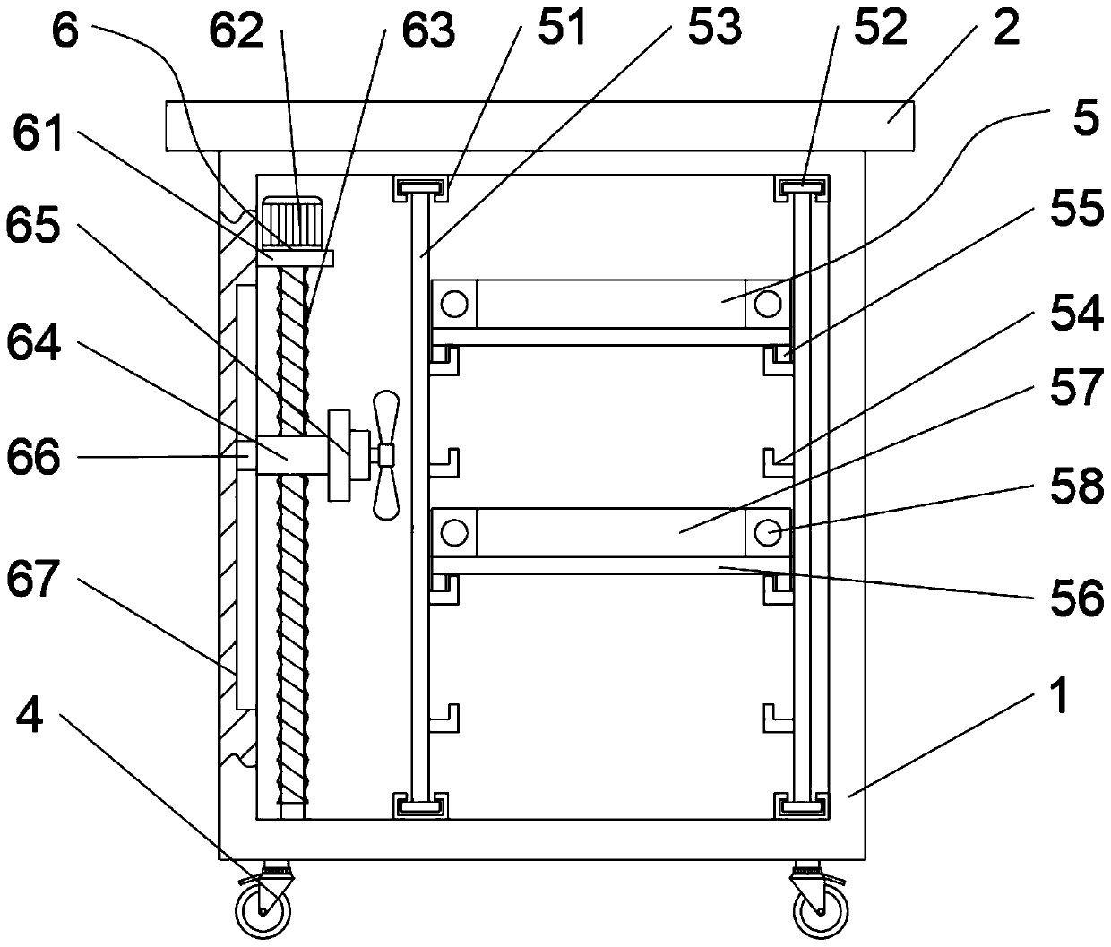
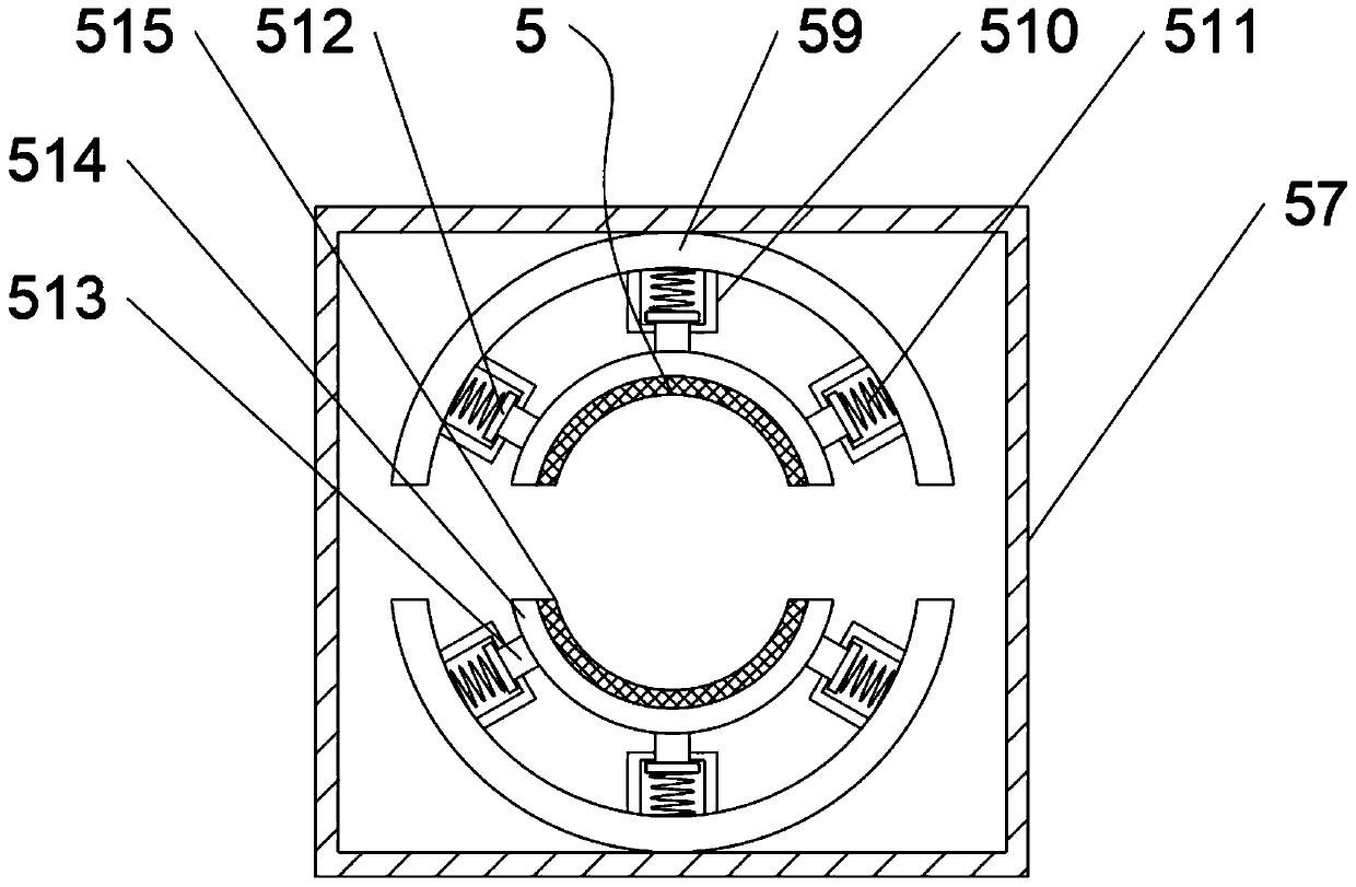
[0020] Such as Figure 1-3 As shown, a computer network line resetter includes a box body 1, a top plate 2, a box door 3, a universal wheel 4, an installation and placement component 5 and a heat dissipation component 6, and a top plate 2 is fixedly installed on the top of the box body 1. One side of the body 1 is connected with a box door 3 through hinge rotation, four universal wheels 4 are fixedly installed at the four corners of the bottom end of the box body 1, and the inner wall of the bottom end of the box body 1 is ...


PUM


Abstract

The invention discloses a computer network line arranging device. The device comprises a box body, a top plate, a box door, universal wheels, an installation and arrangement assembly and a heat dissipation assembly. The top plate is fixedly mounted at a top end of the box body, the box door is rotatably connected to one side of the box body through a hinge, the four universal wheels are fixedly mounted at four corners of a bottom end of the box body, the installation and arranging assembly is arranged on an inner wall of the bottom end of the box body, and the heat dissipation assembly is arranged on one side of the inner wall of the box body. The device is convenient to use, and a problem of disordered arrangement of computer network lines can be effectively solved; a distance between partition plates can be adjusted according to a size of a computer control unit; a space in the box body can be fully utilized, and installation is convenient; network lines can be conveniently arrangedthrough arrangement of an arrangement box, an internal portion of the box is more attractive, meanwhile, the lines are protected against damage; and effective heat dissipation processing can be performed on the control unit through the arrangement of the heat dissipation assembly, and normal operation of a computer network is guaranteed.

Description

technical field [0001] The invention relates to the field of line arranger equipment, in particular to a computer network line arranger. Background technique [0002] Computer network architecture can be described from three aspects: network architecture, network organization, and network configuration. Network organization describes computer networks from two aspects: network physical structure and network realization. Network configuration describes computer networks from network applications The layout of the network, hardware, software and communication lines to describe the computer network, the network architecture is to describe the structure of the computer network from the functional point of view, the computer network is composed of multiple interconnected nodes, and the nodes must constantly exchange data and control Information, in order to exchange data in an orderly manner, each node must abide by a set of reasonable and rigorous structured management system. T...

Claims


Application Information

Patent Timeline
Patent Type & Authority Applications(China)
IPC IPC(8): H05K7/20H02G3/02H02G3/04
CPCH02G3/02H02G3/045H05K7/20136
Inventor 皇甫大恩胡永琰
Owner KAIFENG UNIV
Learn More