
Adjusting supporting device and production line

A technology of supporting device and supporting block, which is applied to the device and coating of the surface coating liquid, which can solve the problems of affecting strength and service life, increasing production cost, and pollution on the back of the product, achieving good fixing effect and reducing production cost, the effect of reducing movement

Pending Publication Date: 2020-05-12
KUNSHAN SAMON AUTOMATION TECH
View PDF0 Cites 5 Cited by
  • Summary
  • Abstract
  • Description
  • Claims
  • Application Information

AI Technical Summary

Problems solved by technology

The main purpose of coating is: solvent-based glue can not only prevent conductive foreign matter from falling on the exposed terminals to cause short circuit, but also prevent the terminals from being exposed to the atmosphere for a long time to cause corrosion and affect the function, or the subsequent engineering operation is improper. , prone to damage and cause adverse effects, affecting strength and service life
[0003] When applying glue to the terminals of the existing display screen, since the glued area is relatively close to the glass edge, it is easy to apply the glue to the carrier during the coating process, resulting in the back of the product behind the automatic line being easily polluted by the glue. Need to hang the coating edge out of the stage
In order to ensure the flatness of the coating area of ​​the product, there must be a support under the coating edge, so that different specifications of products require different sizes of carriers, the versatility is poor, and different types of carriers increase the production cost

Method used

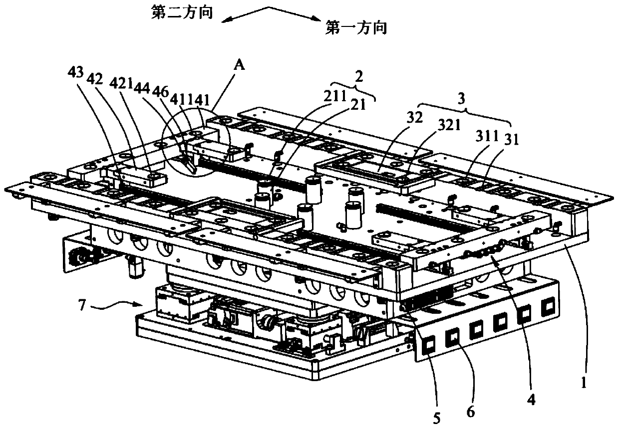
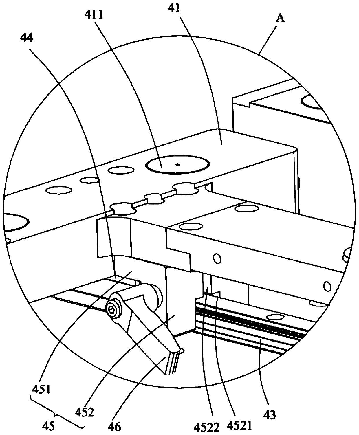
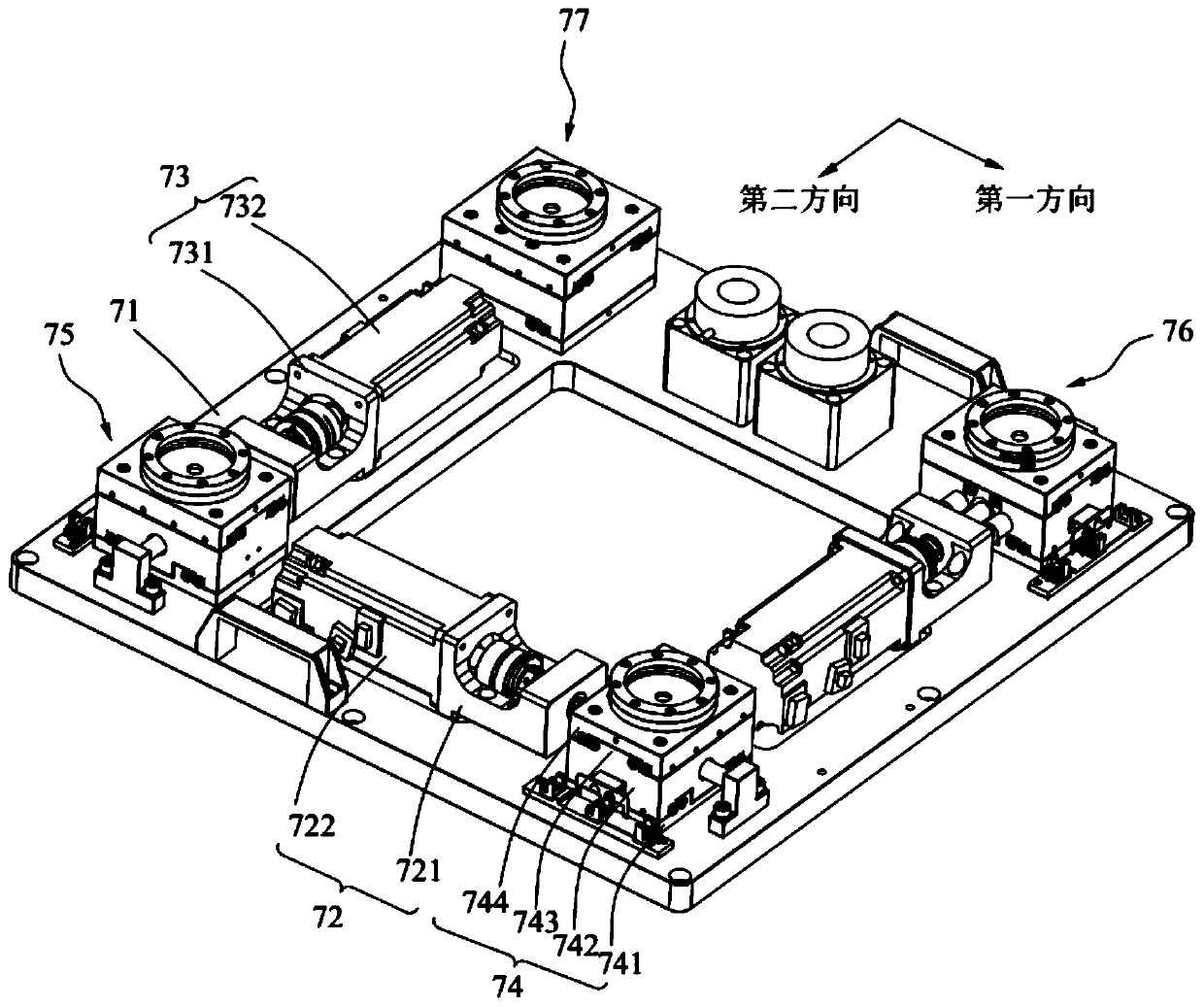

Image

  • Adjusting supporting device and production line
  • Adjusting supporting device and production line
  • Adjusting supporting device and production line

Examples


Embodiment Construction

[0052] In order to make the technical problems solved by the present invention, the technical solutions adopted and the technical effects achieved clearer, the technical solutions of the embodiments of the present invention will be further described in detail below in conjunction with the accompanying drawings. Obviously, the described embodiments are only the technical solutions of the present invention. Some, but not all, embodiments. Based on the embodiments of the present invention, all other embodiments obtained by those skilled in the art without creative efforts fall within the protection scope of the present invention.

[0053] In the description of the present invention, unless otherwise clearly specified and limited, the terms "connected", "connected" and "fixed" should be understood in a broad sense, for example, it can be a fixed connection, a detachable connection, or an integrated ; It can be a mechanical connection or an electrical connection; it can be a direct...


PUM


Abstract

The invention belongs to the technical field of electronic product manufacturing, and discloses an adjusting supporting device and a production line. The adjusting supporting device comprises a bearing plate, a center bearing mechanism, a fixed supporting mechanism and an adjusting supporting mechanism. The center bearing mechanism is arranged in the middle of the bearing plate and used for bearing and fixing the center area of a to-be-machined workpiece. The fixed supporting mechanism is arranged on the bearing plate in the first direction and used for bearing and fixing one set of opposite sides of the to-be-machined workpiece. The adjusting supporting mechanism is arranged on the bearing plate, and the adjusting supporting mechanism and the fixed supporting mechanism are annularly arranged around the center bearing mechanism. According to the length, in the first direction, of the to-be-machined workpiece, the adjusting supporting mechanism is configured to slide relative to the fixed supporting mechanism in the first direction so that the adjusting supporting mechanism can bear and fix the other set of opposite sides of the to-be-machined workpiece. Thus, the adjusting supporting device can adapt to to-be-machined workpieces of multiple specifications, universality is high, and bearing of to-be-machined workpieces of multiple specifications can be achieved by adopting an adjusting platform.

Description

technical field [0001] The invention relates to the technical field of electronic product manufacturing, in particular to an adjustable support device and a production line. Background technique [0002] Electronic products are generally provided with display screens for pattern display. In the actual manufacturing process of the display screen, it is necessary to coat the terminals of the display screen with solvent-based glue, such as Tuffy glue. The main purpose of coating is: solvent-based glue can not only prevent conductive foreign matter from falling on the exposed terminals to cause short circuit, but also prevent the terminals from being exposed to the atmosphere for a long time to cause corrosion and affect the function, or the subsequent engineering operation is improper. , prone to damage and cause adverse effects, affecting strength and service life. [0003] When applying glue to the terminals of the existing display screen, since the glued area is relatively...

Claims


Application Information

Patent Timeline
Patent Type & Authority Applications(China)
IPC IPC(8): B05C13/02
CPCB05C13/02
Inventor 苏山张青山孙浩
Owner KUNSHAN SAMON AUTOMATION TECH
Learn More