Environmentally-friendly glass fiber powder manufacturing and processing raw material cleaning facility

A technology of glass fiber powder and raw material processing, which is applied in the direction of cleaning methods using tools, cleaning methods and utensils, and cleaning methods using liquids, etc., which can solve the problems of impurity adhesion, poor product quality, and incomplete cleaning of glass limit raw materials and other issues to achieve the effect of improving quality, improving effect and avoiding secondary pollution

Active Publication Date: 2020-05-12
天长市天意玻璃制品有限公司
5 Cites 5 Cited by

AI-Extracted Technical Summary

Problems solved by technology

[0005] Aiming at the deficiencies of the prior art, the present invention provides an environment-friendly glass fiber powder production and processing raw material cleaning equipment, which solves the problem that the existing clean...

Method used

As shown in Figure 1-5, the present invention provides a kind of technical scheme: a kind of environment-friendly type glass fiber powder makes processing raw material cleaning equipment, comprises casing 1, and the top of casing 1 is provided with feed inlet, and casing 1 is equipped with a box door and an observation window, and the observation window is made of tempered glass, which facilitates the staff to observe the internal working conditions of the equipment and make work in time. The same circle is fixed between the front and rear side walls of the box body 1. Rod 2, the outer circular surface of round rod 2 is movably sleeved with sleeve 3, and the outer circular surface of sleeve 3 is fixed with inner box 4, and the lower end of the left side wall of inner box 4 is provided with discharge port, and the inner box 4 The left end of the bottom wall is fixed with a triangular guide plate, so as to prevent the water leaking from the leaking net 11 from leaking out from the outlet of the inner box 4, and on the other hand, effectively guide the raw materials exported from the cleaning bucket 10 to the inner box 4 At the discharge port of the inner box 4, the upper end of the left side wall of the inner box 4 is fixed with a fixed plate 5, and the top of the fixed plate 5 is hinged with a hydraulic cylinder 6, and the top of the hydraulic cylinder 6 is hinged with the inner top wall of the box body 1, and the inner box 4 A first telescopic hose 7 is communicated between the top of the top of the box body 1 and the feed port of the box body 1, and the upper end of the inner wall on the left side of the inner box 4 is fixed with a material guide cover 8, and the top of the material guide cover 8 is located at the bottom end of the first telescopic hose 7. Below, and the discharge end of mat...

Abstract

The invention relates to the technical field of glass fiber powder raw material processing, and discloses an environmentally-friendly glass fiber powder manufacturing and processing raw material cleaning facility. The environmentally-friendly glass fiber powder manufacturing and processing raw material cleaning facility comprises a box body. A feeding inlet is formed in the top of the box body. The same circular rod is fixed between the front side wall and the rear side wall of the box body, and a sleeve is movably connected with the excircle face of the circular rod in a sleeving mode. An inner box is fixedly arranged on the excircle face of the sleeve, a discharging outlet is formed in the lower end of the left side wall of the inner box, and a fixing plate is fixedly arranged at the upper end of the left side wall of the inner box. A hydraulic cylinder is movably hinged with the top of the fixing plate, and the top end of the hydraulic cylinder is movably hinged with the inner top wall of the box body. A first stretchable flexible pipe communicates between the top of the inner box and the feeding inlet of the box body, and a material guide cover is fixedly arranged at the upperend of the inner wall of the left side of the inner box. The environmentally-friendly glass fiber powder manufacturing and processing raw material cleaning facility solves the problem that due to thefacts that glass fiber raw materials are not thoroughly cleaned by an existing cleaning facility, and a large number of impurities still adhere to the raw materials after the raw materials are cleaned, the product quality is poor after the raw materials are processed.

Application Domain

Technology Topic

Image

  • Environmentally-friendly glass fiber powder manufacturing and processing raw material cleaning facility
  • Environmentally-friendly glass fiber powder manufacturing and processing raw material cleaning facility
  • Environmentally-friendly glass fiber powder manufacturing and processing raw material cleaning facility

Examples

  • Experimental program(1)

Example Embodiment

[0030] The following will clearly and completely describe the technical solutions in the embodiments of the present invention with reference to the accompanying drawings in the embodiments of the present invention. Obviously, the described embodiments are only some, not all, embodiments of the present invention. Based on the embodiments of the present invention, all other embodiments obtained by persons of ordinary skill in the art without making creative efforts belong to the protection scope of the present invention.
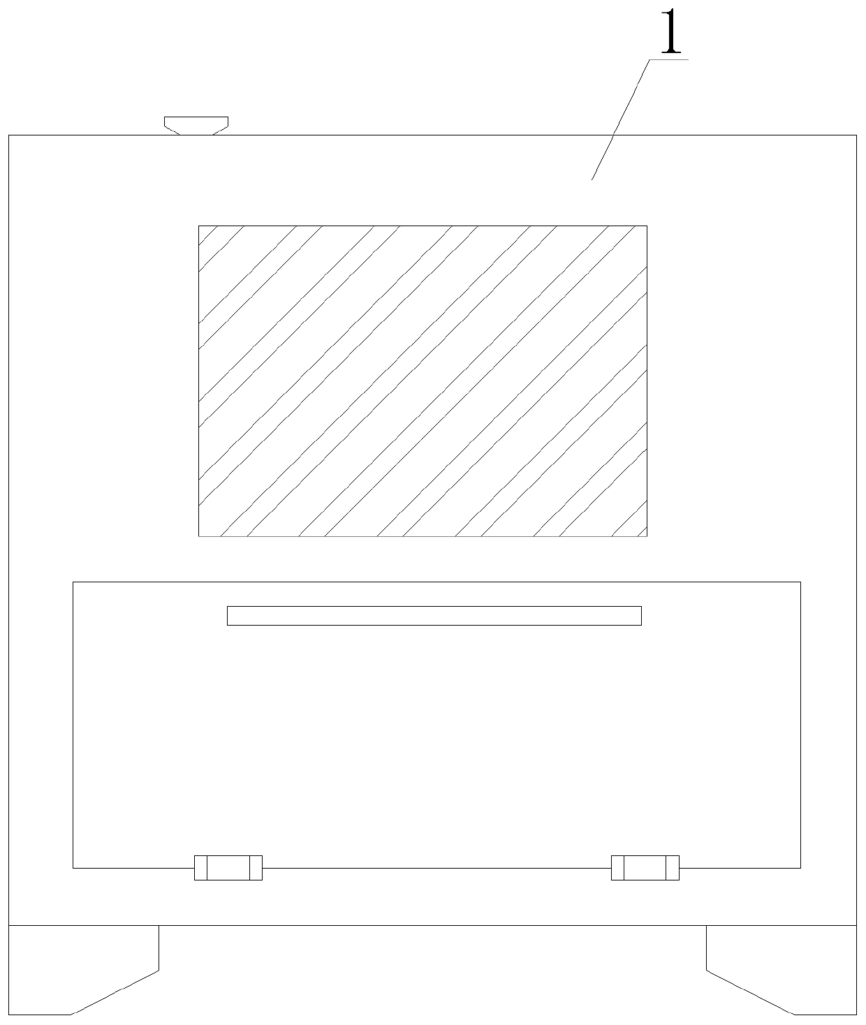
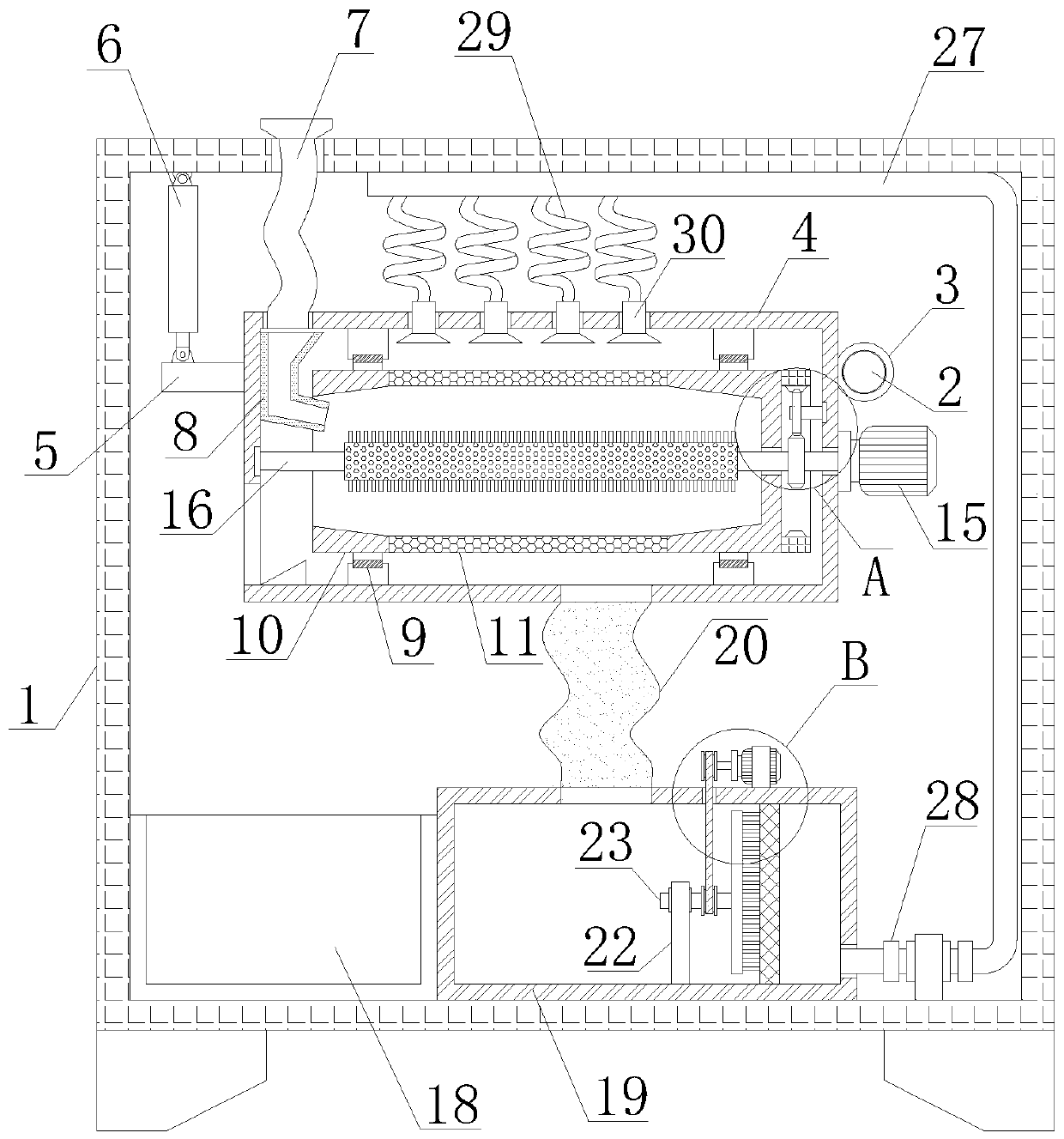
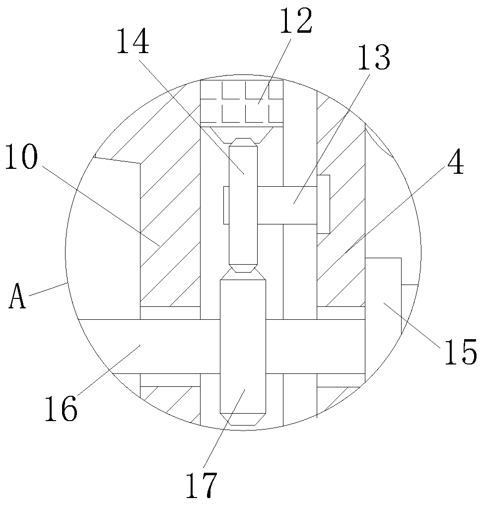
[0031] like Figure 1-5 As shown, the present invention provides a technical solution: an environment-friendly glass fiber powder production and processing raw material cleaning equipment, comprising a box body 1, the top of the box body 1 is provided with a feeding port, and the box body 1 is provided with a box door and an observation Window, and the observation window is made of toughened glass, which facilitates the staff to observe the internal working conditions of the equipment and make work in time. The same round rod 2 is fixed between the front and rear side walls of the box body 1. The circular surface is movable sleeved with a sleeve 3, and the outer circular surface of the sleeve 3 is fixed with an inner box 4, the lower end of the left side wall of the inner box 4 is provided with a discharge port, and the left end of the inner bottom wall of the inner box 4 is fixed with a triangular guide. Plate, in order to prevent the water leaking from the leaking screen 11 from leaking from the outlet of the inner box 4, on the other hand, effectively guide the raw materials exported from the cleaning bucket 10 to the outlet of the inner box 4, and the inner box 4. The upper end of the left side wall is fixed with a fixed plate 5, and the top of the fixed plate 5 is hinged with a hydraulic cylinder 6. The top of the hydraulic cylinder 6 is hinged with the inner top wall of the box body 1. A first telescopic hose 7 is communicated between the feed openings, and a material guide cover 8 is fixed on the upper end of the inner wall on the left side of the inner box 4. The top of the material guide cover 8 is located directly below the bottom end of the first telescopic hose 7, and The discharge end extends to the inside of the cleaning bucket 10. Two fixed bearings 9 are fixed between the inner top wall and the inner bottom wall of the inner box 4 by a fixed block, and the inner ring of the fixed bearing 9 is fixed with a cleaning bucket 10. Two cleaning buckets 10 are fixed. The inside of the end is a conical inclined shape, on the one hand, it is convenient for the raw materials poured into the material guide cover 8 to enter the middle part of the cleaning bucket 10 for cleaning, on the other hand, it prevents the raw materials from leaking out when the cleaning bucket 10 rotates, and the middle part of the outer circular surface of the cleaning bucket 10 There is a filter screen 11, the left side of the cleaning bucket 10 is in the shape of an opening, the filter screen 11 is cylindrical, and the material of the filter screen 11 is stainless steel, which ensures that the water in the nozzle 30 is more convenient to enter, and also facilitates the outflow of waste water after cleaning , the right side wall of the cleaning bucket 10 is fixed with a circular ring 12, the inner ring of the circular ring 12 is provided with a circle of gears, the right inner wall of the inner box 4 is rotatably connected with a rotating rod 13, and the left end of the rotating rod 13 is fixed with a driven gear 14. The driven gear 14 meshes with the gear on the ring 12. The middle part of the right wall of the inner box 4 is fixed with a first motor 15. The output shaft of the first motor 15 is fixed with a brush roller 16, and the left end of the brush roller 16 It runs through the right side wall of the inner box 4 and the right side wall of the cleaning bucket 10 and is rotatably connected with the left side wall of the inner box 4. The shaft of the brush roller 16 is sleeved with a driving gear 17, and the driving gear 17 is meshed with the driven gear 14;
[0032] The inner bottom wall of the box body 1 is fixedly equipped with a receiving box 18 and a water tank 19, a second flexible hose 20 is connected between the top of the water tank 19 and the bottom of the inner box 4, and a filter screen 21 is fixed between the inner walls of the water tank 19 , the inner bottom wall of the water tank 19 is fixed with a support 22, the upper end of the support 22 is rotatably connected with a rotating rod 23, and the right end of the rotating rod 23 is fixed with a strip brush 24, and the bristle end of the strip brush 24 contacts on the filter screen 21 , the top of the water tank 19 is fixedly equipped with a second motor 25, the output shaft of the second motor 25 and the outer circular surface of the rotating rod 23 are fixed with a pulley 26, and the two pulleys 26 are connected by a belt drive, and the belt Through the top of the water tank 19, the lower end of the right side wall of the water tank 19 is connected with a conduit 27, the end of the conduit 27 away from the water tank 19 is a closed end, the conduit 27 is fixedly equipped with a water pump 28, and the water pump 28 is fixed on the inner bottom wall of the tank 1 Above, the end of the conduit 27 away from the water tank 19 extends to the inner top wall of the tank 1, and the outer circular surface of the conduit 27 is communicated with a plurality of rubber hoses 29, and the other end of the rubber hose 29 is fixedly installed with a spray head 30, the spray head 30 is fixed on the inner box 4, and the water spray end of the nozzle 30 runs through and extends to the inside of the inner box 4, the number of the nozzle 30 is four, and the nozzle 30 is located directly above the drain screen 11.
[0033]Further, the top of the water tank 19 is provided with a water tank door. In order to facilitate the cleaning of impurities and water injection after the filter screen is cleaned, the side wall of the water tank 19 is provided with a drainpipe to facilitate the discharge of waste water after use.
[0034] Working principle: When working, start the first motor 15 and the water pump 28 to work, put the raw material from the feeding port, enter the inner box 4 through the first telescopic hose 7, and enter the cleaning bucket through the guidance of the material guide cover 8 10, the first motor 15 drives the brush roller 16 to rotate, and the driving gear 17 cooperates with the driven gear 14 to drive the ring 12 to rotate in reverse. The raw materials inside 10 are rolled by the rotation of the cleaning bucket 10, contacted with the brush roller 16 for cleaning, and the water pump 28 sucks the water in the water tank 19 to the conduit 27, guides the nozzle 30 through the rubber hose 29, sprays evenly on the leakage net 11, and passes through the leakage net 11 The leakage hole enters to clean the raw materials, and the waste water that falls after cleaning enters the water tank 19 through the second telescopic hose 20, and is filtered through the filter screen 21 before being exported for use. After cleaning, start the hydraulic cylinder 6 and push the left end of the inner box 4 downward Move, the inner box 4 is tilted, and the cleaned raw materials are exported from the left end of the cleaning barrel 10, and are collected in the receiving box 18 from the discharge port of the inner box 4;
[0035] When filter screen 21 is cleared, start second motor 25, cooperate with belt pulley 26 and belt, make rotating rod 23 drive strip brush 24 to rotate, to the impurity cleaning of filter screen 21 surfaces.
[0036] The electrical components appearing in this article are all connected with the external main controller and 220V mains electricity, and the main controller can be a conventional known device that plays a control such as a computer.
[0037] It should be noted that in this article, relational terms such as first and second are only used to distinguish one entity or operation from another entity or operation, and do not necessarily require or imply that there is a relationship between these entities or operations. There is no such actual relationship or order between them. Furthermore, the term "comprises", "comprises" or any other variation thereof is intended to cover a non-exclusive inclusion such that a process, method, article, or apparatus comprising a set of elements includes not only those elements, but also includes elements not expressly listed. other elements of or also include elements inherent in such a process, method, article, or device.
[0038] Although the embodiments of the present invention have been shown and described, those skilled in the art can understand that various changes, modifications and substitutions can be made to these embodiments without departing from the principle and spirit of the present invention. and modifications, the scope of the invention is defined by the appended claims and their equivalents.

PUM

no PUM

Description & Claims & Application Information

We can also present the details of the Description, Claims and Application information to help users get a comprehensive understanding of the technical details of the patent, such as background art, summary of invention, brief description of drawings, description of embodiments, and other original content. On the other hand, users can also determine the specific scope of protection of the technology through the list of claims; as well as understand the changes in the life cycle of the technology with the presentation of the patent timeline. Login to view more.

Similar technology patents

Classification and recommendation of technical efficacy words

  • Avoid secondary pollution
  • Improve cleanliness

Washing machine for post insulator

ActiveCN103331272ASafe way of workingAvoid secondary pollutionDirt cleaningCleaning using toolsPower gridPollution flashover
Owner:STATE GRID CORP OF CHINA +1

Automatic ampoule bottle opening device

ActiveCN104787712AAvoid uncontrollable qualityImprove cleanlinessBottle/container closurePower operated devicesScrapAmpoule
Owner:HARBIN INST OF TECH AT WEIHAI

Roman curtain

ActiveUS20110186240A1Improve cleanlinessConvenient replacementExtensible doors/windowsCurtain accessoriesEngineeringMechanical engineering
Owner:LIN SHIH MING
Why Eureka
Try Eureka