A soil nailing wall hole forming device

A hole-forming device and soil nailing wall technology, which is applied to earth movers/excavators, construction, etc., can solve the problems of large inclination angle error of soil nail holes and the angle cannot be adjusted at will, so as to reduce labor intensity and ensure stability Sexuality and ease of use

Active Publication Date: 2022-05-03
THE 5TH ENG OF CHINA RAILWAY 22TH BUREAU GROUP +1
View PDF0 Cites 0 Cited by
  • Summary
  • Abstract
  • Description
  • Claims
  • Application Information

AI Technical Summary

Problems solved by technology

[0003] Aiming at the defects in the prior art that the inclination angle of the soil nail hole is large and the angle cannot be adjusted at will, the invention discloses a soil nail wall hole-forming device, and the device of the invention can be used to adjust the soil nail at will according to the construction needs At the same time, the stability of the equipment during use is high, which effectively reduces the hole-forming error of the soil nail hole, and greatly improves the construction quality and construction efficiency.

Method used


Image

  • A soil nailing wall hole forming device
  • A soil nailing wall hole forming device
  • A soil nailing wall hole forming device

Examples


Embodiment approach 1

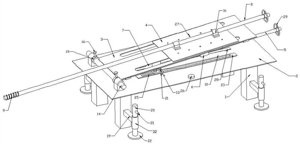
[0039] This embodiment, as the basic embodiment of the present invention, discloses a soil nailing wall hole-forming device, the specific structure is as follows figure 1 As shown, it includes a frame 1, the top of the frame 1 is fixedly provided with a workbench 2, and one end of the workbench 2 is fixedly provided with an articulated shaft 14, and two sets of connecting supports are rotatably connected on the articulated shaft 14 through a rotating pair. Ears 15, the two connecting lugs 15 are fixedly connected with the console 3 at the same time, so as to realize the hinged connection between the workbench 2 and the console 3, and at the same time, the connecting lugs 15 are also threaded with locking bolts 16, The fixing of the console is realized by pressing the end face of the locking bolt 16 against the end face of the hinge shaft 14;

[0040] The first baffle plate 23 and the second baffle plate 24 parallel to each other are fixedly arranged on the workbench 2, and the...

Embodiment approach 2

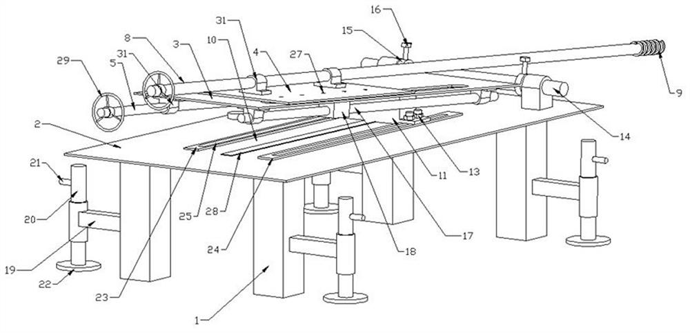
[0043] As a preferred embodiment of the present invention, this embodiment discloses a soil nailing wall hole-forming device, including a frame, and the specific structure is as follows: Figure 1 to Figure 7 As shown, it includes a frame 1, the frame 1 is provided with a workbench 2, the workbench 2 is hinged with an operation table 3, and the operation table 3 is slidably provided with a movable workbench 4, and the operation table 3 The bottom surface is fixedly provided with a sliding rod 17 through the connecting seat, and a chute 7 is also provided on the operating table 3. The bottom surface of the movable workbench 4 is fixedly provided with a linear bearing seat 18, and the linear bearing seat 18 passes through the chute 7 and the sliding rod. 17 interactive connection;

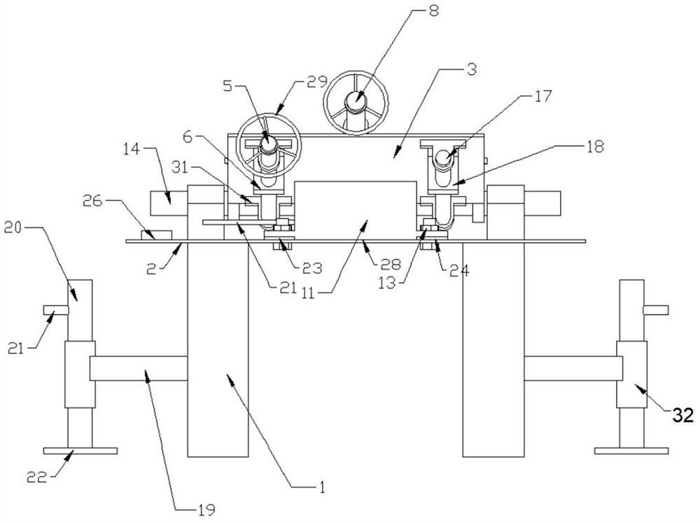
[0044] Further, connecting rods 19 are fixedly arranged on the four legs of the frame 1, and the second connecting sleeve 32 is welded on the connecting rod 19, and the inner thread of the second con...

Embodiment approach 3

[0047] This embodiment, as another preferred embodiment of the present invention, discloses a soil nailing wall hole forming device, the specific structure is as follows Figure 8 As shown, a workbench 2 is included, an operation platform 3 is hinged on the workbench 2, and a scissor lifting frame 30 is fixedly connected to the bottom surface of the workbench 2 at the same time.

[0048] When the present invention is in use, first place the whole set of equipment at the working point, and carry out leveling through horizontal air bubbles, then change the inclination angle of the console to a specified angle by changing the position of the adjustment block, and then adjust the rotating shaft after the console is fixed. The rotating wheel drives the drill bit to rotate, while the drill bit rotates, the movable worktable is continuously pushed forward by rotating the adjusting screw, and then the drill bit is continuously pushed into the hole;

[0049] Compared with the prior art...


PUM


Abstract

The invention provides a soil nailing wall opening device, comprising a frame, a workbench is arranged on the frame, an operation platform is connected to one end of the workbench, and a movable workbench is slidably arranged on the operation platform, and the movable workbench A rotating shaft with a drill bit is installed on the top; at the same time, an adjustment block for adjusting the inclination angle of the console is provided on the workbench. The angle can be adjusted freely, and the inclination angle of the drill bit is fixed during the operation, which can effectively control the drilling error, and the worker can realize the rapid excavation of the soil nail hole only by turning the drill bit. Compared with the traditional Luoyang shovel, it is more convenient to use , labor-saving.

Description

technical field [0001] The invention relates to the technical field of foundation pit construction equipment, in particular to a soil nailing wall hole-forming device. Background technique [0002] Soil nail wall is an in-situ soil reinforcement technology. The slope of the foundation pit is reinforced by soil nails made of steel bars. A steel mesh is laid on the surface of the slope, and a layer of concrete surface is sprayed to combine with the earthwork slope. The slope reinforced support construction method, its structure is a composite body formed by the solid bonding of the reinforced rods (i.e. soil nails or anchor rods) set in the slope body and the surrounding soil, and the similar structure formed by the surface layer. The support structure of the gravity retaining wall; in the construction process of the soil nail wall, it is necessary to open a soil nail hole with a certain depth and an inclination angle in the soil layer, and then insert the soil nail into the s...

Claims


Application Information

Patent Timeline
Patent Type & Authority Patents(China)
IPC IPC(8): E02F5/18E02F5/16
CPCE02F5/18E02F5/16
Inventor 李经纬宋伟王伟高彦李东营程金库崔杰
Owner THE 5TH ENG OF CHINA RAILWAY 22TH BUREAU GROUP
Why Eureka
Try Eureka