Dehumidification system and dehumidification method thereof

A technology of anode wires and pins, which is applied in the program control of sequence/logic controllers, electrical program control, construction, etc., to achieve the effect of solving waterproof and moisture-proof problems

Pending Publication Date: 2020-05-12
长沙同强电子科技有限公司
View PDF0 Cites 10 Cited by
  • Summary
  • Abstract
  • Description
  • Claims
  • Application Information

AI Technical Summary

Problems solved by technology

[0005] The purpose of the present invention is to provide a dehumidification system and dehumidification method to effectively solve the waterproof and moisture-proof problem of the underground layer of the building structure

Method used


Image

  • Dehumidification system and dehumidification method thereof
  • Dehumidification system and dehumidification method thereof
  • Dehumidification system and dehumidification method thereof

Examples


Embodiment 1

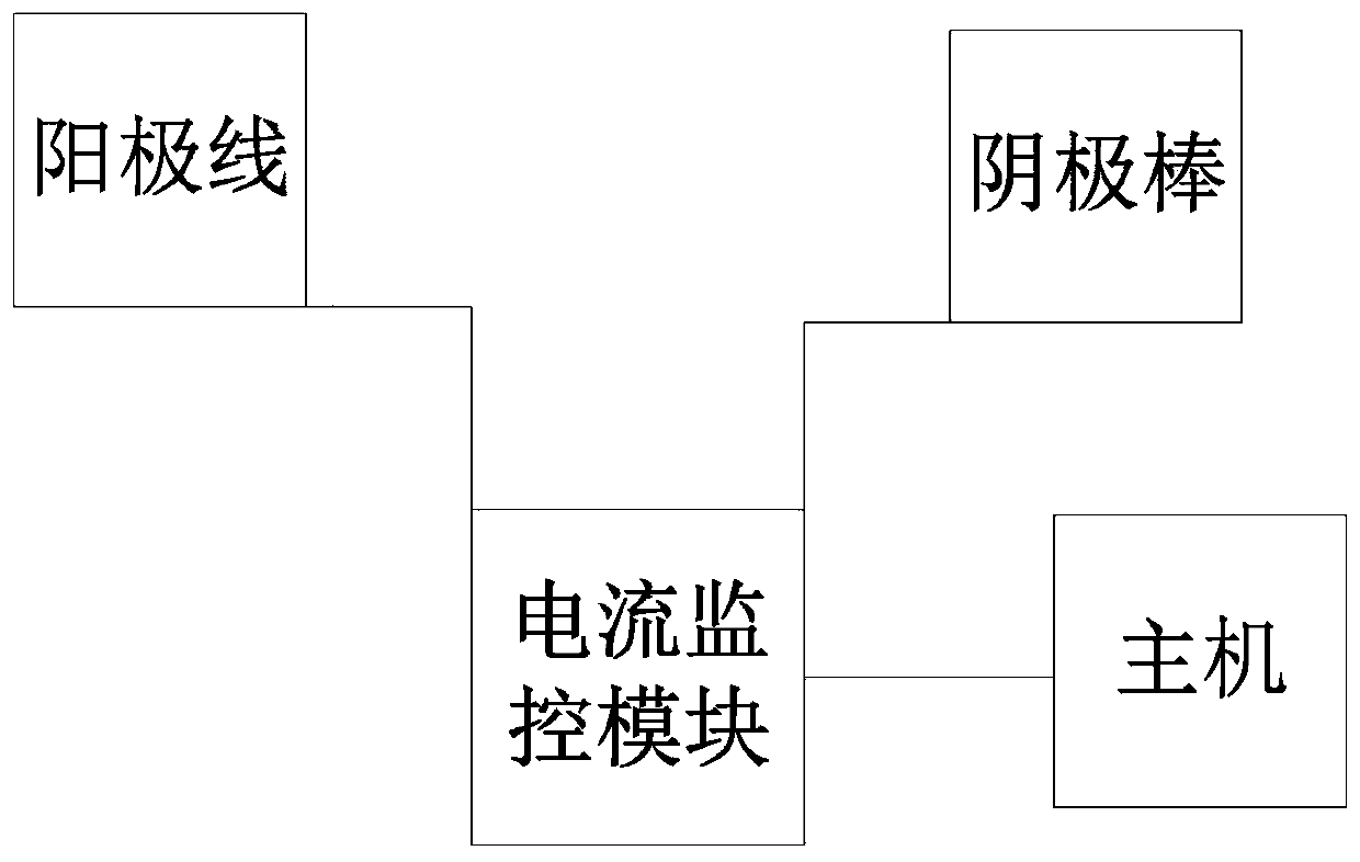
[0041] This embodiment provides a dehumidification system, including:

[0042] Anode wire, the anode wire is embedded in the wall of the structure to be tested, and is used to conduct positive current to the wall of the structure to be tested;

[0043] A cathode rod inserted into the soil at a set distance from the wall of the structure to be tested for conducting negative current into the soil;

[0044] The current monitoring module is used to generate positive current and send it to the anode wire according to the monitoring command, and to send the negative current to the cathode rod; it is also used to obtain the drying information of the structure to be tested according to the change of the current data, and send the drying information to the host ;

[0045] The host is used to generate monitoring instructions, and is also used to receive drying information and optimize monitoring instructions according to the drying information;

[0046]The current monitoring module is...

Embodiment 2

[0067] Corresponding to the above-mentioned embodiment 1, this embodiment provides a dehumidification method applied to the dehumidification system described in the above-mentioned embodiment 1, including:

[0068] Obtain the dry and wet degree information of the wall or ground of the basement to be tested, and send the dry and wet degree information to the host;

[0069] The host computer generates monitoring instructions according to the dryness and humidity information and sends them to the current monitoring module. The monitoring instructions include positive pulse signals and negative pulse signals containing time information;

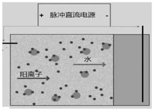
[0070] The current monitoring module generates a positive pulse current and a negative pulse current corresponding to the time according to the monitoring instruction, sends the positive pulse current corresponding to the time to the anode wire, and sends the negative pulse current corresponding to the time to the cathode rod.

[0071] As a prefe...


PUM


Abstract

The invention, which relates to the technical field of building waterproofing technology, discloses a dehumidification system and a dehumidification method thereof in order to effectively realize waterproofing and moisture resistance of an underground layer of a building. The dehumidification system comprises: an anode line, buried in the wall of a to-be-measured structure and used to conduct positive current to the wall of the to-be-measured structure; a cathodic rod, inserted into the soil at a set distance from the wall of the to-be-measured structure and used to conduct negative current into the soil; a current monitoring module, used to generate positive current and send to the anode line according to monitoring instruction, generate negative current and send to the cathode rod, and obtain drying information of the to-be-measured structure according to changes of current data and send the drying information to a host; and the host, used to produce the monitoring instruction, receive the drying information, and optimize the monitoring instruction according to the drying information. The current monitoring module is connected to the anode line and the cathode rod respectively and is connected to the host through communication cables.

Description

technical field [0001] The invention relates to the technical field of building structure waterproofing, in particular to a dehumidification system and a dehumidification method thereof. Background technique [0002] With the rapid development of society, there are more and more buildings of various types and higher and higher. However, most underground space development technologies are in the initial stage. In real life, water seepage often occurs in the underground layer. When water seepage occurs in the walls or other structures of the underground layer, it is easy to cause damp and moldy problems, and further make The ambient air where people live becomes dirty, reducing the quality of people's daily life. In addition, severe water seepage will also bring other disadvantages, such as corroding buildings or steel bars, increasing maintenance costs, and shortening the structural life of buildings. [0003] At present, people generally prevent water seepage including: bu...

Claims


Application Information

Patent Timeline
Patent Type & Authority Applications(China)
IPC IPC(8): E04B1/70G05B19/04
CPCE04B1/70E04B1/7007G05B19/04
Inventor 谢翔之
Owner 长沙同强电子科技有限公司
Why Eureka
Try Eureka