
Variable pitch system of wind power generation set and wind power generation set

A technology for wind turbines and pitch systems, which is applied in wind turbine combinations, wind energy power generation, wind turbines, etc., can solve the problem of increasing the clearance between the pitch drive gear and the pitch bearing gear, aggravating the pitch drive gear and the pitch bearing gear. Wear and other problems to achieve the effect of reducing wear

Active Publication Date: 2020-05-12
CSIC CHONGQING HAIZHUANG WINDPOWER EQUIP
View PDF12 Cites 3 Cited by
  • Summary
  • Abstract
  • Description
  • Claims
  • Application Information

AI Technical Summary

Problems solved by technology

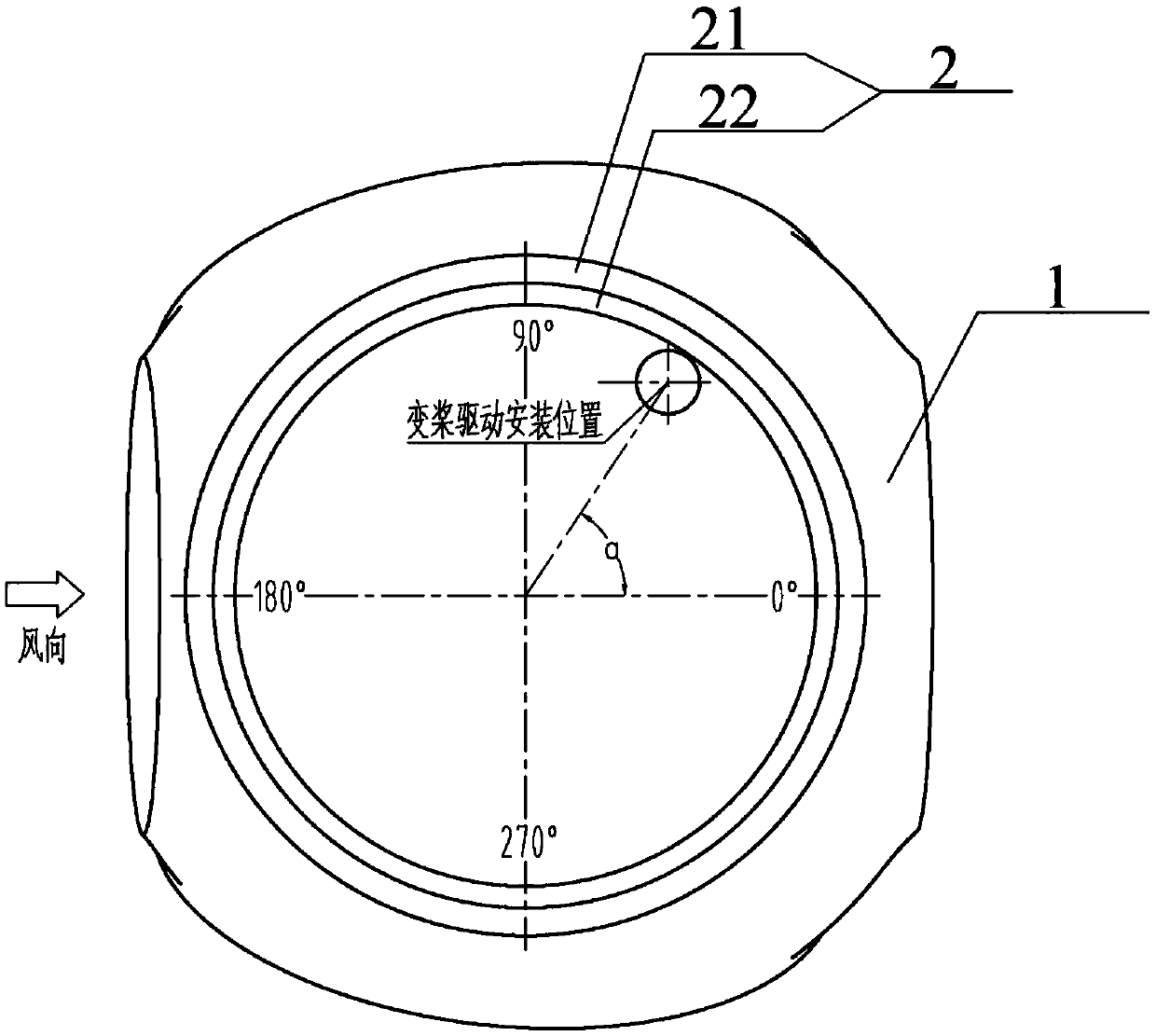
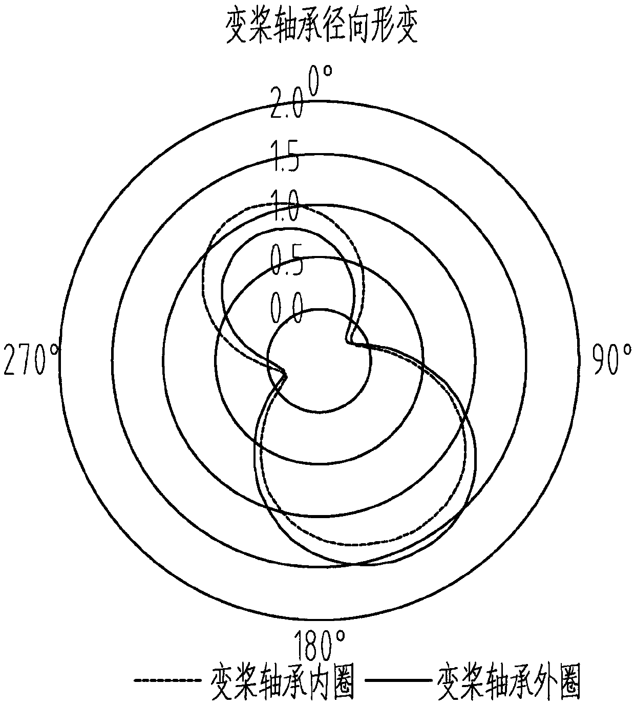
[0003] In the existing wind turbine pitch system, the pitch drive is mostly arranged in the area where the fatigue damage of the wheel hub is relatively small or in the area where it is easy to install, but it does not fully consider the radial direction of the inner ring and the outer ring when the pitch bearing is running. Therefore, during the operation of the pitch bearing, the position of the pitch bearing may cause an opening when the pitch drive gear meshes with the pitch bearing gear, that is, the pitch drive gear and the pitch Increased clearance between bearing gears increases wear between pitch drive gear and pitch bearing gear

Method used


Image

  • Variable pitch system of wind power generation set and wind power generation set
  • Variable pitch system of wind power generation set and wind power generation set
  • Variable pitch system of wind power generation set and wind power generation set

Examples


Embodiment Construction

[0021] The following will clearly and completely describe the technical solutions in the embodiments of the present invention with reference to the accompanying drawings in the embodiments of the present invention. Obviously, the described embodiments are only some, not all, embodiments of the present invention. Based on the embodiments of the present invention, all other embodiments obtained by persons of ordinary skill in the art without making creative efforts belong to the protection scope of the present invention.

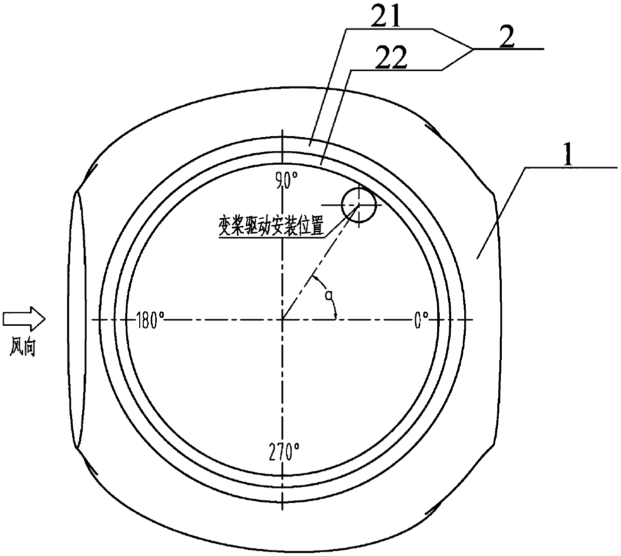
[0022] See figure 1 , which shows a schematic structural diagram of a wind turbine pitch system provided by an embodiment of the present invention, including a hub 1, a pitch bearing 2, and a pitch drive. The pitch bearing 2 includes an outer ring 21, an inner ring 22, and an outer sleeve The ring 21 is connected with the hub 1, the inner ring 22 is used for connecting with the blade, and the pitch bearing 2 is provided with a pitch bearing gear, wherein:

[...


PUM


Abstract

The invention discloses a variable pitch system of a wind power generation set and the wind power generation set. The variable pitch system of the wind power generation set comprises a wheel hub, a variable pitch bearing and a variable pitch driver. The variable pitch bearing comprises an outer ferrule and an inner ferrule. The outer ferrule is connected to the wheel hub, and the inner ferrule isconnected to a blade. A variable pitch bearing gear is arranged on the variable pitch bearing. The variable pitch driver is mounted in a selected area and is engaged to a gear of the variable pitch bearing through a gear of the variable pitch driver. The selected area is an area where the radial deformation of the outer ferrule and the inner ferrule is smaller than a preset value. According to thetechnical scheme provided by the invention, the variable pitch driver is mounted in the area where the radial deformation of the outer ferrule and the inner ferrule of the variable pitch bearing is smaller than the preset value. When the variable pitch bearing operates, as the variable pitch driver is mounted in the area where the radial deformation of the outer ferrule and the inner ferrule is relatively small, an opening when the gear of the variable pitch driver is engaged to the gear of the variable pitch bearing can be reduced to the greatest extent, so that wear between the gear of thevariable pitch driver and the gear of the variable pitch bearing can be reduced.

Description

technical field [0001] The present invention relates to the technical field of wind turbines, and more specifically, to a wind turbine pitch system and a wind turbine. Background technique [0002] With the decrease of traditional energy sources and the increasingly prominent environmental problems, wind energy with the characteristics of reproducibility and cleanliness has been widely used. Using wind turbines to convert wind energy into electrical energy is one of the main ways to utilize wind energy. Among them, the wind turbine mainly includes the main drive system, the pitch system, and the yaw system. Through the cooperation of these systems, the conversion of wind energy can be completed. [0003] In the existing wind turbine pitch system, the pitch drive is mostly arranged in the area where the fatigue damage of the wheel hub is relatively small or in the area where it is easy to install, but it does not fully consider the radial direction of the inner ring and the ...

Claims


Application Information

Patent Timeline
Patent Type & Authority Applications(China)
IPC IPC(8): F03D7/02F03D80/70F03D80/30F03D15/00F03D9/25
CPCF03D7/0224F03D9/25F03D15/00F03D80/30F03D80/70Y02E10/72
Inventor 谭术平仵文松韩佳肖长远曾昌勇
Owner CSIC CHONGQING HAIZHUANG WINDPOWER EQUIP
Learn More