
Building construction quality real-time detection device

A real-time detection and building construction technology, applied in the direction of measuring devices, mechanical measuring devices, and mechanical devices, can solve the problems of cumbersome and inconvenient operation steps, inconvenient leveling and cleaning operations, waste of manpower, etc., and achieve simple, convenient and smooth operation of measurement readings Labor-saving and efficient cleaning process

Inactive Publication Date: 2020-05-12
张猛
View PDF1 Cites 2 Cited by
  • Summary
  • Abstract
  • Description
  • Claims
  • Application Information

AI Technical Summary

Problems solved by technology

[0005] The purpose of the present invention is to provide a real-time detection device for building construction quality, to solve the problems of the above-mentioned background technology on the remaining concrete on the main test support plate after the test and the missing soil dregs produced during the filling process, leveling and cleaning operations It is inconvenient, and it needs to be scraped off with an external hanging board for many times, which is time-consuming and laborious. In addition, it is necessary to move the conical barrel and use the tapered barrel as a reference to measure with the help of an external tape measure or ruler. This operation process requires Many people participate, waste manpower, the operation steps are cumbersome and inconvenient, and the practicability is poor

Method used


Image

  • Building construction quality real-time detection device
  • Building construction quality real-time detection device
  • Building construction quality real-time detection device

Examples


Embodiment Construction

[0030] The following will clearly and completely describe the technical solutions in the embodiments of the present invention with reference to the accompanying drawings in the embodiments of the present invention. Obviously, the described embodiments are only some, not all, embodiments of the present invention.

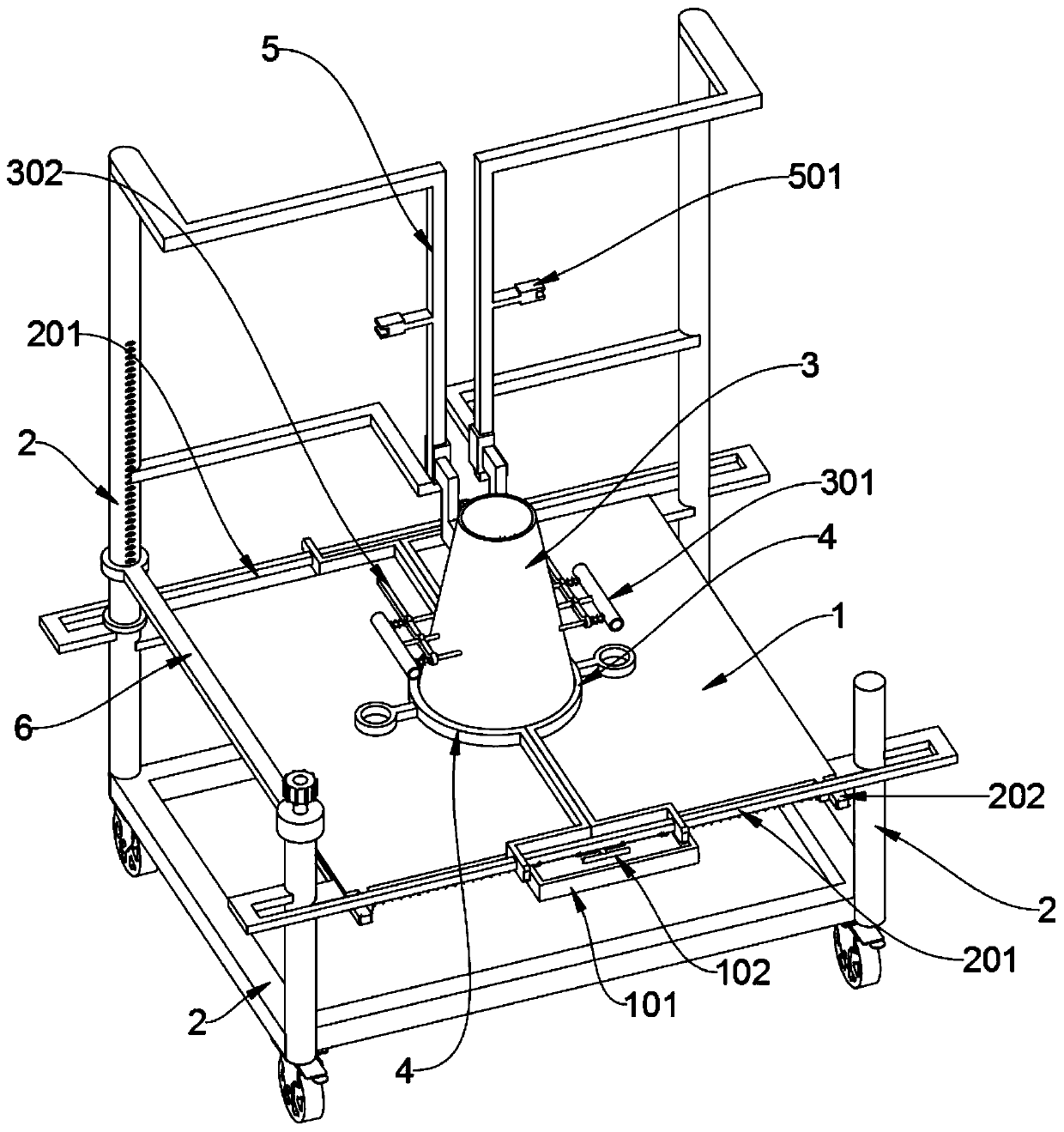
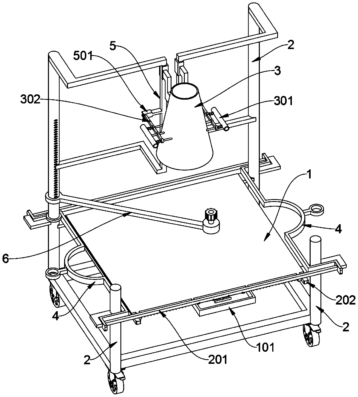
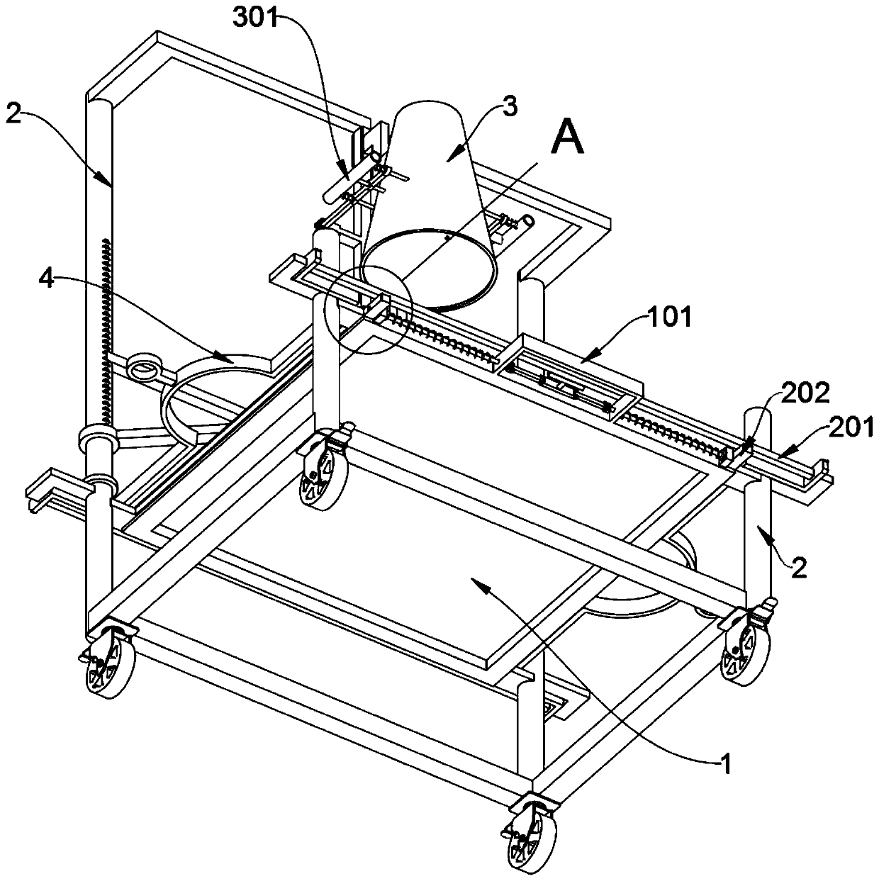
[0031] see Figure 1 to Figure 8 , an embodiment provided by the present invention: a real-time detection device for building construction quality, including a support shaft 2 and a material-holding cone 3, the four support shafts 2 are symmetrically supported front and back, and a square base frame is welded at the bottom, the square The bottom of the base frame is symmetrically installed with four wheels; when the filling cone 3 slides down and is placed on the center of the support plate 1, the left and right sliding frames 4 can be slidably attached to the bottom of the filling cone 3 On the outer wall of the circumference; the filling cone 3 includes a lever 301...


PUM


Abstract

The invention discloses a real-time detection device for building construction quality, relates to the technical field of construction detection devices, and solves the problems that an existing detection device is inconvenient to level and clean residual concrete on a main body test support plate after test and omitted soil slag generated in the filling process, an external hanging plate is needed for scraping for multiple times, and time and labor are wasted. The building construction quality real-time detection device comprises four supporting shafts and a material containing conical barrel, the four supporting shafts symmetrically support in the front-back direction, square base frames are welded to the bottoms of the supporting shafts, and four wheels are symmetrically installed at the bottoms of the square base frames; when the material containing conical barrel slides downwards to abut against the center of a supporting table plate, a left sliding wiping frame and a right sliding wiping frame can be attached to an outer wall of the bottom circumference of the material containing conical barrel in a sliding and clamping mode. A T-shaped pull rod and two inserting shafts jointly form a double-connecting-rod drawing and inserting nail mechanism, and the two inserting shafts can be synchronously drawn and slid only by holding and pulling the T-shaped pull rod, so that the loosening of the supporting table plate is completed conveniently.

Description

technical field [0001] The invention relates to the technical field of construction detection devices, in particular to a real-time detection device for building construction quality. Background technique [0002] Concrete slump mainly refers to the plasticizing performance and pumpability of concrete. Factors affecting concrete slump mainly include gradation change, water content, weighing deviation of scales, and the amount of admixture. There is the temperature of cement, etc. Slump refers to the workability of concrete, specifically to ensure the normal progress of construction, including water retention, fluidity and cohesion of concrete. The test method of slump is to use a slump cylinder with the diameter of the upper opening smaller than that of the lower opening, pour concrete into it and fill it three times. , smooth out. Then pull up the barrel, and the concrete will slump due to its own weight. The height of the highest point of the concrete after the barrel i...

Claims


Application Information

Patent Timeline
Patent Type & Authority Applications(China)
IPC IPC(8): G01B5/06
CPCG01B5/061
Inventor 张猛
Owner 张猛
Learn More