Monitoring method, device and system

A monitoring terminal and real-time monitoring technology, which is applied in the field of monitoring methods, devices and systems, can solve problems such as high cost and poor monitoring effect, and achieve the effect of reducing monitoring cost, improving monitoring effect, and efficient monitoring

Pending Publication Date: 2020-05-12
BEIJING HUANENG XINRUI CONTROL TECH
View PDF6 Cites 0 Cited by
  • Summary
  • Abstract
  • Description
  • Claims
  • Application Information

AI Technical Summary

Problems solved by technology

[0004] The embodiment of the present invention provides a monitoring method, device and system to at least solve the technical problems of relying on a third-party real-time database to realize real-time monitoring in the prior art, resulting in high cost and poor monitoring effect

Method used


Image

  • Monitoring method, device and system
  • Monitoring method, device and system
  • Monitoring method, device and system

Examples


Embodiment 1

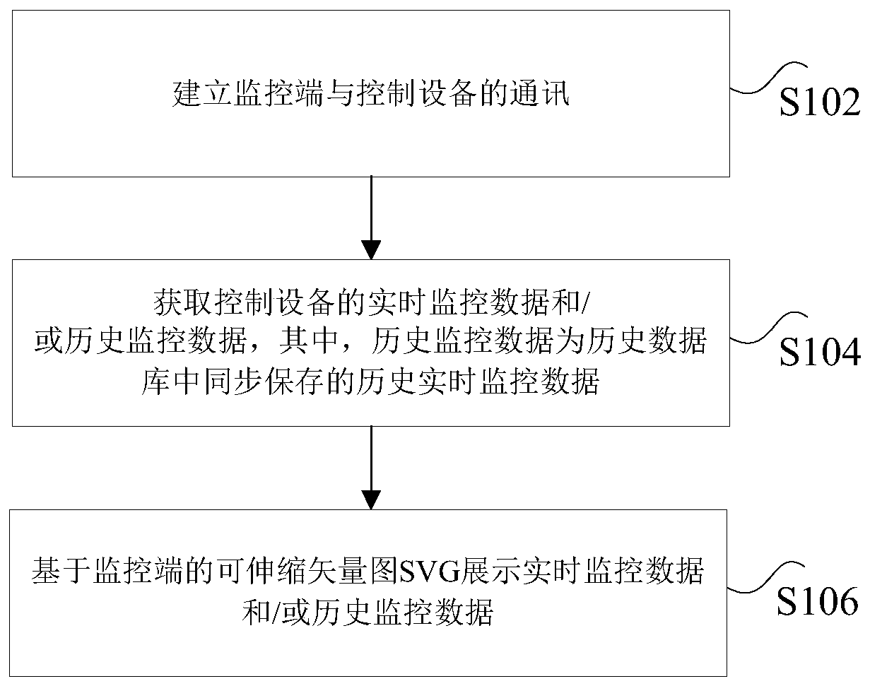
[0023] According to an embodiment of the present invention, an embodiment of a monitoring method is provided. It should be noted that the steps shown in the flowcharts of the accompanying drawings can be executed in a computer system such as a set of computer-executable instructions, and, although in The flowcharts show a logical order, but in some cases the steps shown or described may be performed in an order different from that shown or described herein.

[0024] figure 1 is a flowchart of a monitoring method according to an embodiment of the present invention, such as figure 1 As shown, the method includes the following steps:

[0025] Step S102, establishing communication between the monitoring terminal and the control device;

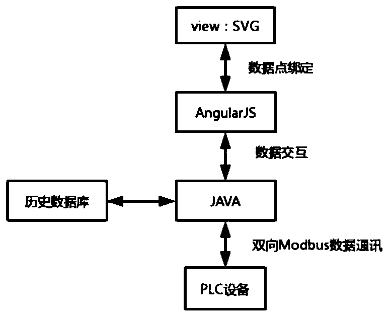
[0026] The above-mentioned monitoring terminal includes but is not limited to a remote monitoring terminal; the above-mentioned control device includes but is not limited to a single-chip microcomputer and a PLC. It should be noted that the est...

Embodiment 2

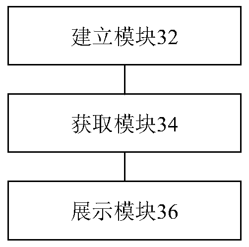
[0096] According to another aspect of the embodiments of the present invention, a monitoring device is also provided, image 3 is a schematic diagram of a monitoring device according to an embodiment of the present invention, such as image 3 As shown, the monitoring device includes the following modules: an establishment module 32 , an acquisition module 34 and a display module 36 , and the monitoring device will be described in detail below.

[0097] Build module 32, be used for setting up the communication of monitoring terminal and control device;

[0098] The obtaining module 34 is connected to the above-mentioned establishing module 32, and is used to obtain real-time monitoring data and / or historical monitoring data of the control equipment, wherein the historical monitoring data is historical real-time monitoring data synchronously preserved in the historical database;

[0099] The display module 36 is connected to the acquisition module 34 and is used for d...

Embodiment 3

[0108] According to another aspect of the embodiments of the present invention, a monitoring system is also provided, including the above monitoring device.

[0109] It should be noted that, in a specific implementation process, the above-mentioned monitoring system includes but is not limited to any one of the above-mentioned monitoring devices.


PUM


Abstract

The invention discloses a monitoring method, device and system. The method comprises the following steps: establishing communication between a monitoring end and control equipment; obtaining real-timemonitoring data and/or historical monitoring data of the control equipment, wherein the historical monitoring data are/is historical real-time monitoring data synchronously stored in a historical database; and displaying the real-time monitoring data and/or historical monitoring data based on a scalable vector diagram SVG of a monitoring end. The technical problems that in the prior art, real-time monitoring depends on a third-party real-time database, and consequently the cost is too high and the monitoring effect is poor are solved.

Description

technical field [0001] The present invention relates to the technical field of equipment monitoring, in particular to a monitoring method, device and system. Background technique [0002] Most of the existing monitoring methods based on scalable vector graphics (Scalable Vector Graphics, referred to as SVG) technology only focus on the development of front-end display. A set of independent monitoring solutions; as a result, this method has a strong dependence, because according to the different collection points, the cost of purchasing a third-party real-time database every time is too high. Moreover, the implementation of existing methods only focuses on real-time monitoring, ignoring historical retrospect. Due to lack of basis, it is impossible to effectively solve a series of subsequent problems. [0003] For the above problems, no effective solution has been proposed yet. Contents of the invention [0004] Embodiments of the present invention provide a monitoring met...

Claims


Application Information

Patent Timeline
Patent Type & Authority Applications(China)
IPC IPC(8): G06F11/30
CPCG06F11/3065G06F11/3003
Inventor 孙建龙田宏哲杨政厚王雅宾
Owner BEIJING HUANENG XINRUI CONTROL TECH
Why Eureka
Try Eureka