Battery formation constant-temperature equipment and control method

A technology of battery formation and constant temperature equipment, which is applied in the control of the battery formation constant temperature equipment, and in the field of battery formation constant temperature equipment, which can solve the problems of the influence of the temperature field distribution of the equipment cabinet, the fluctuation of the flow field of the equipment cabinet, and the uneven temperature of the equipment cabinet. Achieve the effect of maintaining flow field, realizing temperature and maintaining stability

Active Publication Date: 2020-05-12
ZHUHAI TITANS NEW POWER ELECTRONICS CO LTD
View PDF9 Cites 3 Cited by
  • Summary
  • Abstract
  • Description
  • Claims
  • Application Information

AI Technical Summary

Problems solved by technology

When the fan starts and stops, it will inevitably cause the flow field fluctuation in the equipment cabinet, which will affect the temperature field distribution in the equipment cabinet, resulting in uneven temperature in the equipment cabinet

Method used


Image

  • Battery formation constant-temperature equipment and control method
  • Battery formation constant-temperature equipment and control method
  • Battery formation constant-temperature equipment and control method

Examples


Embodiment Construction

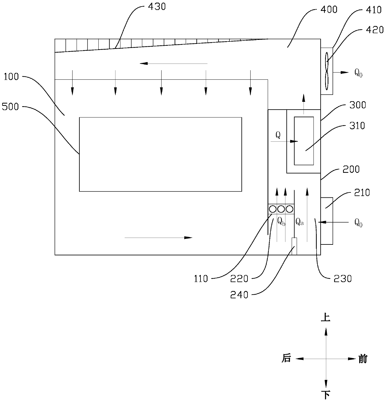
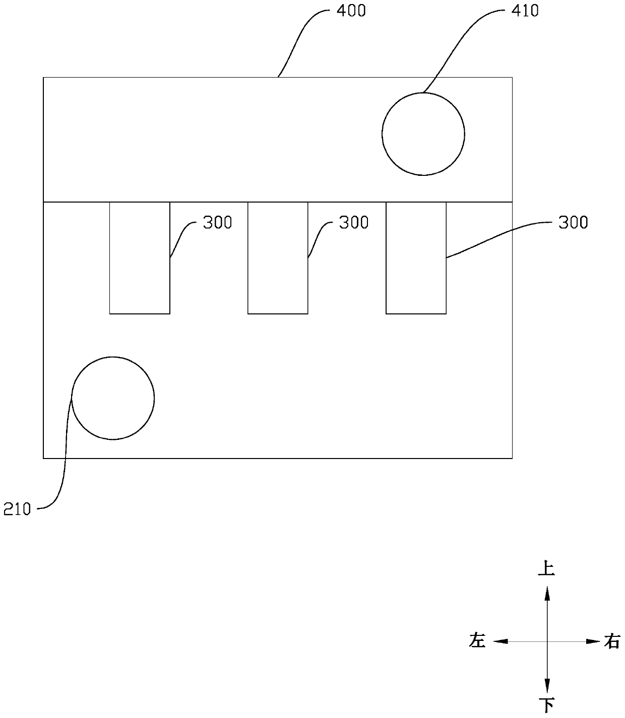
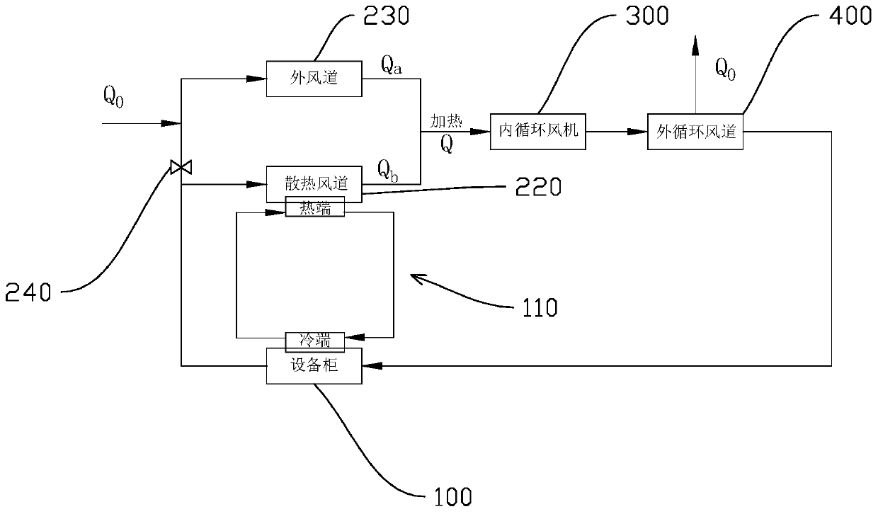
[0033] Embodiments of the present invention are described in detail below, examples of which are shown in the drawings, wherein the same or similar reference numerals designate the same or similar elements or elements having the same or similar functions throughout. The embodiments described below by referring to the figures are exemplary only for explaining the present invention and should not be construed as limiting the present invention.

[0034] In the description of the present invention, it should be understood that the orientation descriptions, such as up, down, front, back, left, right, etc. indicated orientations or positional relationships are based on the orientations or positional relationships shown in the drawings, and are only In order to facilitate the description of the present invention and simplify the description, it does not indicate or imply that the device or element referred to must have a specific orientation, be constructed and operated in a specific ...


PUM


Abstract

The invention discloses battery formation constant-temperature equipment and a control method. The battery formation constant-temperature equipment comprises a controller, an equipment cabinet, an internal circulation air duct, an internal circulation fan and a heat exchanger. A heat exchanger cold end is arranged in the equipment cabinet, and a plurality of temperature sensors electrically connected with the controller are arranged in the equipment cabinet. The internal circulation air duct communicates with the equipment cabinet, and an air inlet communicating with the outside is formed in the internal circulation air duct. A heating device is arranged at the air inlet of the internal circulation fan, the air inlet is further communicated with the internal circulation air duct, and an air outlet communicates with the equipment cabinet. The inner circulation air duct comprises a heat dissipation air duct and an outer air duct, the starting point of the heat dissipation air duct communicates with the air inlet through an air valve, the air valve is electrically connected with the controller, the starting point of the outer air duct communicates with the air inlet, and the heat exchanger partially extends into the heat dissipation air duct. According to the technical scheme, temperature control is achieved by controlling the indirect heat exchange efficiency, impressions on a flow field in the equipment cabinet are avoided, and stable and uniform distribution of the temperature field in the equipment cabinet can be achieved.

Description

technical field [0001] The invention relates to the field of battery formation, in particular to a constant temperature equipment for battery formation, and a control method for controlling the constant temperature equipment for battery formation. Background technique [0002] Battery formation and the first charge and discharge of the newly produced new battery at a certain temperature, the temperature during the formation process will have an impact on the capacity and electrochemical performance of the battery. During the mass production process, it is necessary to maintain a uniform temperature in the equipment to ensure that the produced batteries have high consistency. [0003] In the prior art, since the equipment cabinet has a certain heat preservation performance, and a high-power fan is often used for heat dissipation, in order to keep the temperature in the equipment cabinet constant, the fan needs to be started and stopped frequently. When the fan starts and sto...

Claims


Application Information

Patent Timeline
Patent Type & Authority Applications(China)
IPC IPC(8): H01M10/44H01M10/613H01M10/615H01M10/635H01M10/6563
CPCH01M10/446H01M10/613H01M10/615H01M10/635H01M10/6563Y02E60/10
Inventor 邱立国张文科胡全友蔡琳
Owner ZHUHAI TITANS NEW POWER ELECTRONICS CO LTD
Why Eureka
Try Eureka