Full-automatic wire stripping machine

A wire stripping machine, fully automatic technology, used in cable installation devices, electrical components, equipment for dismantling/armoring cables, etc., can solve the problems of high labor intensity, high production cost, low wire stripping efficiency, etc. Low labor and cost, and the effect of improving wire stripping efficiency

Pending Publication Date: 2020-05-12
GUANGDONG POWER GRID CO LTD +1
View PDF0 Cites 4 Cited by
  • Summary
  • Abstract
  • Description
  • Claims
  • Application Information

AI Technical Summary

Problems solved by technology

[0004] Aiming at the deficiencies of the prior art, the present invention provides a fully automatic wire stripping machine, which solves the existing problems of the existing wire strippers such as complex structure, high production cost, troublesome maintenance, and the problem of fixing cables When it is necessary to manually tighten or manually twist the bolts for fixing, the labor intensity is high and the stripping efficiency is low.

Method used


Image

  • Full-automatic wire stripping machine
  • Full-automatic wire stripping machine
  • Full-automatic wire stripping machine

Examples


Embodiment 1

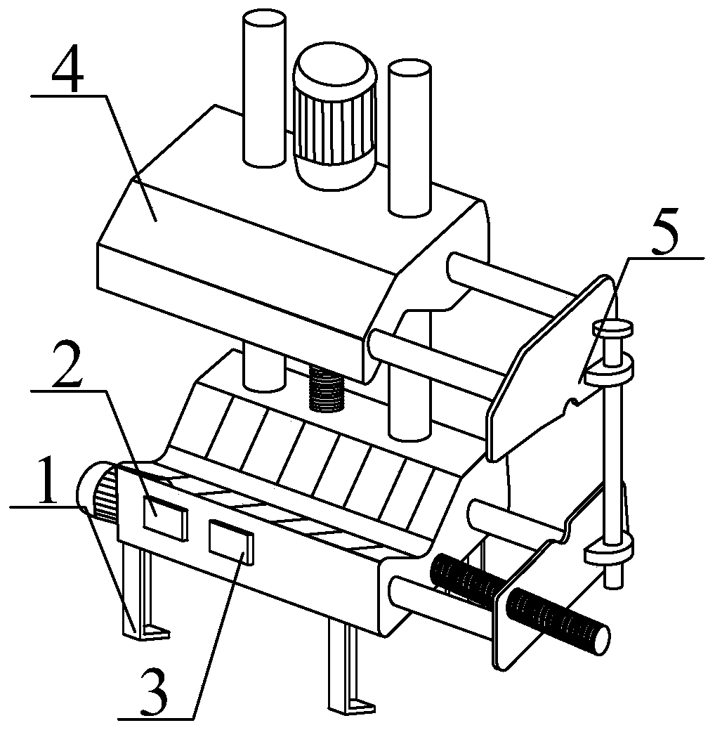
[0019] Such as Figure 1-3 As shown, the present invention provides a technical solution: a fully automatic wire stripping machine, including a leg 1, a first controller 2, a second controller 3, a cable clamping device 4 and a wire stripping mechanism 5, the described There are 4 supporting legs 1, which are respectively welded to the four corners of the bottom of the bottom clamp seat 41; the first controller 2 and the second controller 3 are installed on one side of the bottom clamp seat 41 by screws, and are connected to the 36V battery connection; the stripping mechanism 5 is detachably connected to the cable clamping device 4 .

Embodiment 2

[0021] A fully automatic wire stripping machine, comprising a leg 1, a first controller 2, a second controller 3, a cable clamping device 4 and a wire stripping mechanism 5, the four legs 1 are welded on the bottom At the four corners of the bottom of the clamp base 41; the first controller 2 and the second controller 3 are installed on one side of the bottom clamp base 41 by screws, and are connected with the 36V battery; the stripping mechanism 5 is connected with the cable The clamping device 4 is detachably connected.

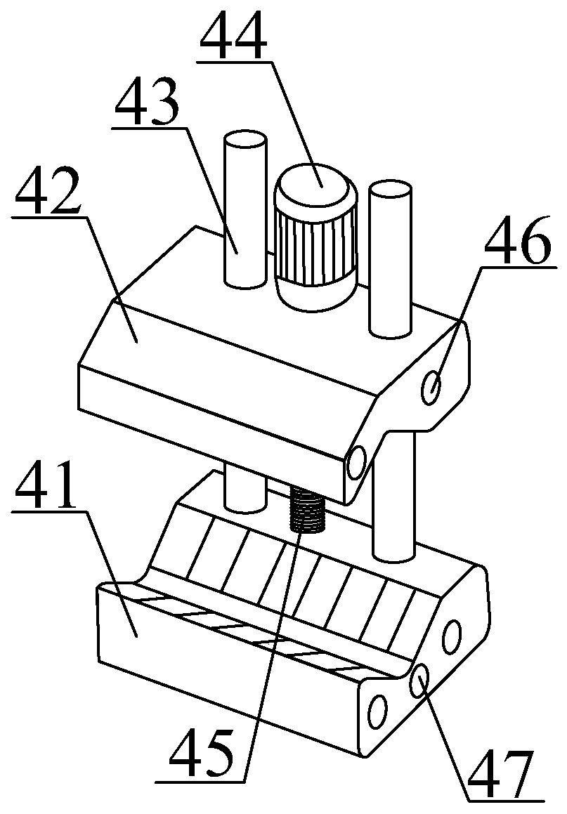
[0022] Preferably, the cable clamping device 4 includes a bottom clamp seat 41, an upper clamp seat 42, a guide rod 43, a first motor 44, a first screw rod 45, a guide hole 46 and a through hole 47, and the bottom clamp seat 41 Both the upper end and the lower end of the upper clamping seat 42 are provided with V-shaped grooves; the upper clamping seat 42 is sleeved on the guide rod 43; two guide rods 43 are used and welded on one side of the upper end of t...

Embodiment 3

[0024] A fully automatic wire stripping machine, comprising a leg 1, a first controller 2, a second controller 3, a cable clamping device 4 and a wire stripping mechanism 5, the four legs 1 are welded on the bottom At the four corners of the bottom of the clamp base 41; the first controller 2 and the second controller 3 are installed on one side of the bottom clamp base 41 by screws, and are connected with the 36V battery; the stripping mechanism 5 is connected with the cable The clamping device 4 is detachably connected.

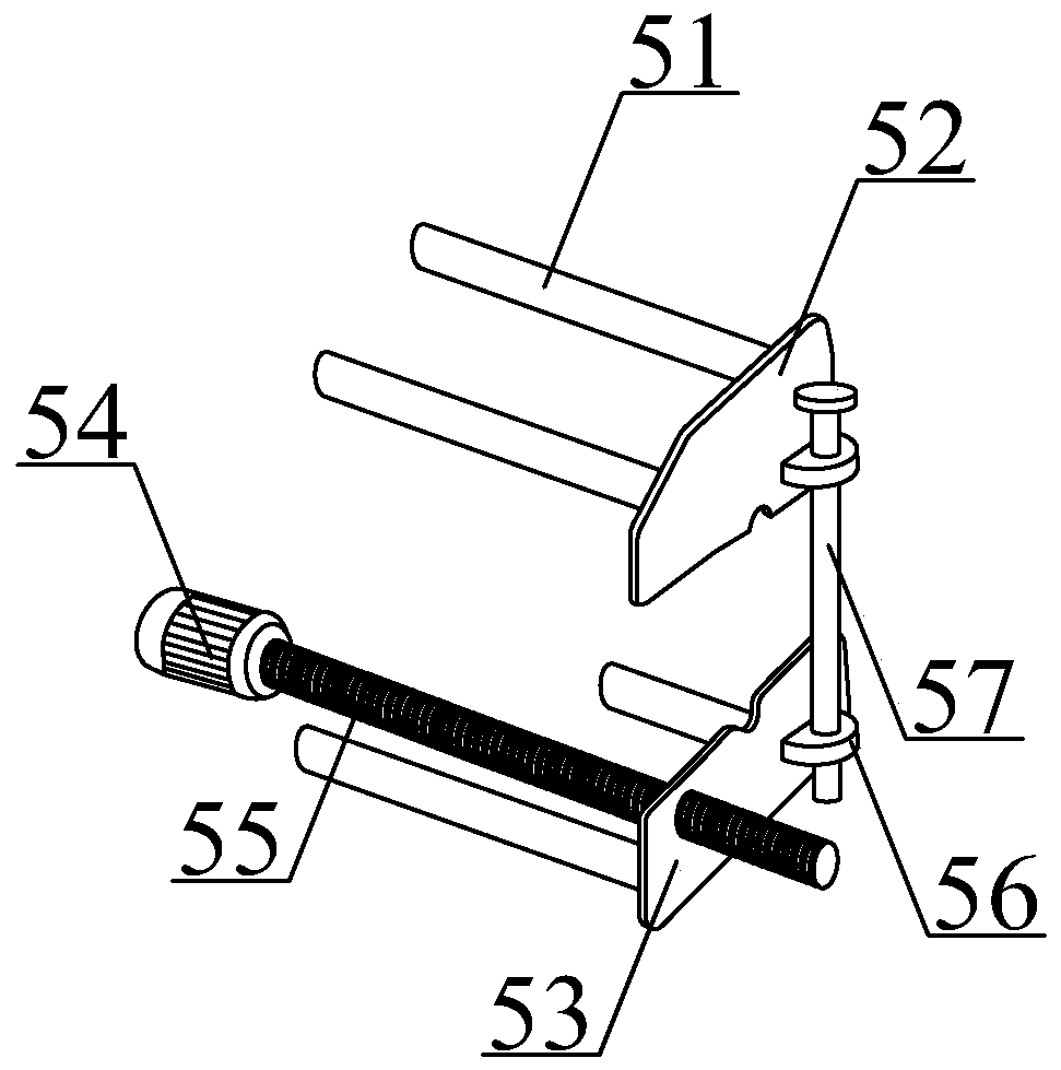
[0025] Preferably, the stripping mechanism 5 includes a slide bar 51, an upper splint 52, a lower splint 53, a second motor 54, a second screw 55, a linkage ear 56 and a T-bar 57, and the slide bar 51 adopts four , 2 as a group, respectively vertically welded with the upper splint 52 and the lower splint 53; the second motor 54 is installed on the left side of the bottom clamp seat 41 through bolts; the left end of the second screw 55 is passed through a co...


PUM


Abstract

The invention discloses a full-automatic wire stripping machine, and the wire stripping machine comprises supporting legs, a first controller, a second controller, a cable clamping device and a cablestripping mechanism. The cable clamping device comprises a bottom clamping seat; the four supporting legs are welded to the four corners of the bottom of the bottom clamping seat respectively. The first controller and the second controller are both installed at one side of the bottom clamping seat through screws and connected with a 36V storage battery. The cable stripping mechanism is detachablyconnected with the cable clamping device. By arranging the cable clamping device, the cable clamping effect is achieved, and manual labor is reduced. According to the invention, through the arrangement of the wire stripping mechanism, during the clamping of the cable, an upper clamping plate and a lower clamping plate are driven by a sliding rod to be clamped at the position where the cable needsto be stripped, and then a second motor drives a second screw to rotate, the upper clamping plate converts the rotating motion of the second screw into linear motion, and the cable stripping mechanismstarts to drive away from the cable clamping device, thereby achieving the cable stripping under a large driving force, and improving the cable stripping efficiency of equipment.

Description

technical field [0001] The invention relates to the technical field of wire strippers, in particular to a fully automatic wire stripper. Background technique [0002] With the continuous expansion of the scale of distribution network construction, the workload of distribution network operation and maintenance is also increasing. In order to improve the reliability of power supply and reduce the number of users during power outages, the importance of live work is gradually increasing. In the line welding construction process, the stripping of the insulated wire sheath is an important process in the wire stripping and splicing. [0003] However, the existing wire strippers still have complex structures, high production costs, and relatively troublesome maintenance. When the cables are fixed, they need to be manually tightened or manually screwed to fix the bolts. The labor intensity is high, and the wire stripping The problem of low efficiency. Contents of the invention ...

Claims


Application Information

Patent Timeline
Patent Type & Authority Applications(China)
IPC IPC(8): H02G1/12
CPCH02G1/1251H02G1/1273
Inventor 杨芳
Owner GUANGDONG POWER GRID CO LTD
Why Eureka
Try Eureka