Supercharge Your Innovation With Domain-Expert AI Agents!

Generating circuit for generating analog waveforms with same ascending and descending slopes

A technology for simulating waveforms and generating circuits, applied in the direction of pulse generation, electrical components, pulse technology, etc., can solve the problems of complex circuits and difficult applications, and achieve the effect of temperature insensitivity, cost and complexity reduction, and control mode.

Active Publication Date: 2020-05-12
LANZHOU INST OF PHYSICS CHINESE ACADEMY OF SPACE TECH
View PDF9 Cites 0 Cited by
  • Summary
  • Abstract
  • Description
  • Claims
  • Application Information

AI Technical Summary

Problems solved by technology

However, this method has the disadvantage of complex circuit, and it is difficult to apply it in a relatively simple power supply.

Method used


Image

  • Generating circuit for generating analog waveforms with same ascending and descending slopes
  • Generating circuit for generating analog waveforms with same ascending and descending slopes

Examples


Embodiment Construction

[0013] The present invention will be described in detail below with reference to the accompanying drawings and examples.

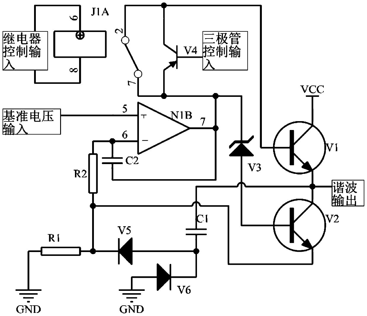
[0014] The invention provides a generating circuit that generates analog waveforms with the same rising and falling slopes, such as figure 1 As shown, it includes operational amplifier N1B, compensation resistor R2, compensation capacitor C2, integral capacitor C1, charge control bipolar transistor V1, discharge control bipolar transistor V2, Zener diode V3, loop control diode I V5, loop control diode II V6, switch control bipolar transistor V4, electromagnetic relay J1A and sampling resistor R1;

[0015] The positive input terminal of the operational amplifier N1B inputs an external reference voltage, the negative input terminal is respectively connected to the compensation resistor R2 and the first terminal of the compensation capacitor C2, and the output terminal is respectively connected to the second terminal of the compensation capacitor C2 and the s...


PUM


Abstract

The invention discloses a generating circuit for generating analog waveforms with the same ascending and descending slope. The generating circuit comprises an operational amplifier N1B, a compensationresistor R2, a compensation capacitor C2, an integrating capacitor C1, a charge control bipolar transistor V1, a discharge control bipolar transistor V2, a voltage stabilizing diode V3, a loop control diode I V5, a loop control diode II V6, a switch control bipolar transistor V4, an electromagnetic relay J1A and a sampling resistor R1. According to the invention, the use number of operational amplifiers is minimized by using a small number of analog devices and adopting a charge-discharge circuit separation design method; simulation waveforms with the same ascending and descending slopes aregenerated, and the cost and complexity of the waveform generator are reduced.

Description

technical field [0001] The invention belongs to the technical field of waveform generating circuits, in particular to a generating circuit for generating analog waveforms with the same rising and falling slopes. Background technique [0002] Because multi-channel power supply products often require a certain turn-on and turn-off sequence, and electrical equipment needs to be turned on first and then turned off, and the turn-on interval is the same as the turn-off interval. The prior art can be controlled by means of analog circuit or digital circuit control. [0003] The analog circuit control method can indirectly adjust the order and interval by adjusting the start-up time for each of the multiple power supplies, but this method has the problem that it can only control the start-up sequence, but it is difficult to control the shutdown sequence. It is also possible to use a dedicated timing control chip, such as LM3881, for control, but this method can only give timing sig...

Claims


Application Information

Patent Timeline
Patent Type & Authority Applications(China)
IPC IPC(8): H03K4/06
CPCH03K4/06
Inventor 孟渊李斌戈焰武荣康婷汪晓文
Owner LANZHOU INST OF PHYSICS CHINESE ACADEMY OF SPACE TECH
Features
  • R&D
  • Intellectual Property
  • Life Sciences
  • Materials
  • Tech Scout
  • Unparalleled Data Quality
  • Higher Quality Content
  • 60% Fewer Hallucinations
Learn More