A Prefabricated Panel Covering Maintenance Process
A prefabricated board, lamination technology, applied in the direction of manufacturing tools, thin material processing, ceramic molding machines, etc., can solve the cost of film damage, can not directly complete lamination, lamination and film cutting, power devices, etc. problem, to achieve the effect of reducing production cost, good adhesion effect and high processing efficiency
- Summary
- Abstract
- Description
- Claims
- Application Information
AI Technical Summary
Problems solved by technology
Method used
Image
Examples
Embodiment 1
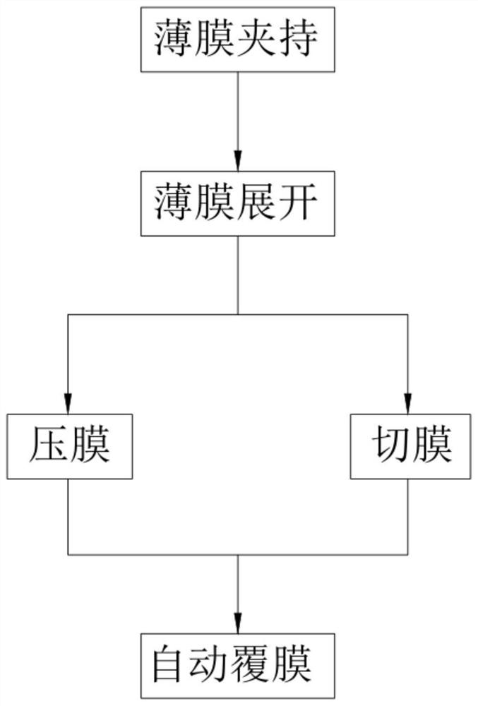
[0093] Such as figure 1 As shown, a prefabricated panel coating maintenance process, including:
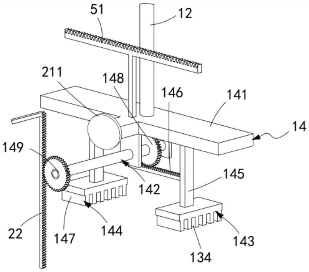
[0094] Step 1, the film is clamped, the vertical push assembly 12 is started, the active part 142 on the clamping assembly 14 cooperates with the first driving part 22, the reciprocating part a143 and the reciprocating part b144 move towards each other, and the prefabricated board on the sandwich board a132 is completed 20 to carry out the clamping work, at this time, the clamping assembly 14 is located at the sliding track 212 input end of the horizontal push assembly 21;
[0095] Step 2, the film is unfolded, and when the cylinder b214 of the horizontal push assembly 21 is extended, the push block 2111 pushes the sliding block 1471 on the sandwich plate b147 to slide along the lower layer of the sliding track 212, and the sliding block 211 pushes the limit plate 213 to continue sliding toward The output end of track 212 slides;
[0096] Step 3, film pressing, when the clamping...
Embodiment 2
[0109] The following will clearly and completely describe the technical solutions in the embodiments of the present invention with reference to the accompanying drawings in the embodiments of the present invention. Obviously, the described embodiments are only some, not all, embodiments of the present invention.
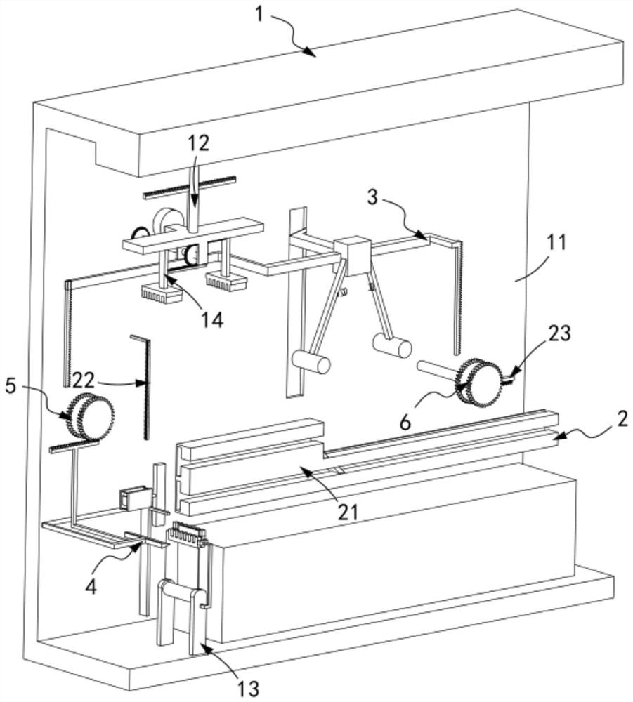
[0110] Such as figure 2 , Figure 17 As shown, a fully automatic laminating machine for prefabricated panel maintenance, including:
[0111] The film head positioning mechanism 1, the film head positioning mechanism 1 includes a frame 11, a vertical push assembly 12 installed on the top of the frame 11 and reciprocating horizontally on the frame 11, and a vertical push assembly 12 installed on the frame 11 The lower film loading assembly 13 and the clamping assembly 14 located above the film loading assembly 13 and fixedly connected to the telescopic end of the vertical pushing assembly 12;
[0112] A flattening mechanism 2, the flattening mechanism 2 includes a f...
Embodiment 3
[0166] Such as Figure 14 , Figure 16 As shown, the parts that are the same as or corresponding to those in the second embodiment are marked with the corresponding reference numerals in the second embodiment. For the sake of simplicity, only the differences from the second embodiment will be described below. The difference between this embodiment three and embodiment two is:
[0167] further, such as Figure 13 As shown, the film cutting mechanism 4 includes:
[0168] A translation rod 41, the translation rod 41 is slidably arranged on the frame 11, and one end thereof is fixed on the frame 11 by a spring c;
[0169] A cutting knife 42, said cutting knife 42 is fixedly arranged on the other end of said translation rod 41; and
[0170] The baffle 43 , the baffle 43 is fixedly arranged on the clamping plate a132 on the side close to the laminating mechanism 3 and arranged linearly with the cutter 42 .
[0171] It is worth mentioning here that by setting the film cutting me...
PUM
 Abstract
Description
Claims
Application Information
 - R&D
- Intellectual Property
- Life Sciences
- Materials
- Tech Scout
- Unparalleled Data Quality
- Higher Quality Content
- 60% Fewer Hallucinations
Browse by: Latest US Patents, China's latest patents, Technical Efficacy Thesaurus, Application Domain, Technology Topic, Popular Technical Reports.
© 2025 PatSnap. All rights reserved.Legal|Privacy policy|Modern Slavery Act Transparency Statement|Sitemap|About US| Contact US: help@patsnap.com


