An intelligent power equipment installation lifting device

A technology of power equipment and lifting devices, which is applied in the direction of lifting devices, lifting frames, etc., can solve the problems of inconvenient installation, increased work intensity, and difficulty in manual handling and unloading, so as to achieve convenient installation, reduce work intensity, and reduce labor costs Effect

Active Publication Date: 2021-05-04
中惺有限公司
View PDF5 Cites 1 Cited by
  • Summary
  • Abstract
  • Description
  • Claims
  • Application Information

AI Technical Summary

Problems solved by technology

[0005] Aiming at the deficiencies in the prior art, the purpose of the present invention is to provide an intelligent power equipment installation lifting device to solve the problem that the prior art needs to lift the power equipment onto the flat plate because the lifting device is usually flat, and When it is necessary to unload the electrical equipment, it is also necessary to remove it. Since the electrical equipment is usually heavy, it is not easy to have more manpower to carry and unload it at a high place, which makes it more inconvenient to install and increases the work intensity. question

Method used


Image

  • An intelligent power equipment installation lifting device
  • An intelligent power equipment installation lifting device
  • An intelligent power equipment installation lifting device

Examples


Embodiment 1

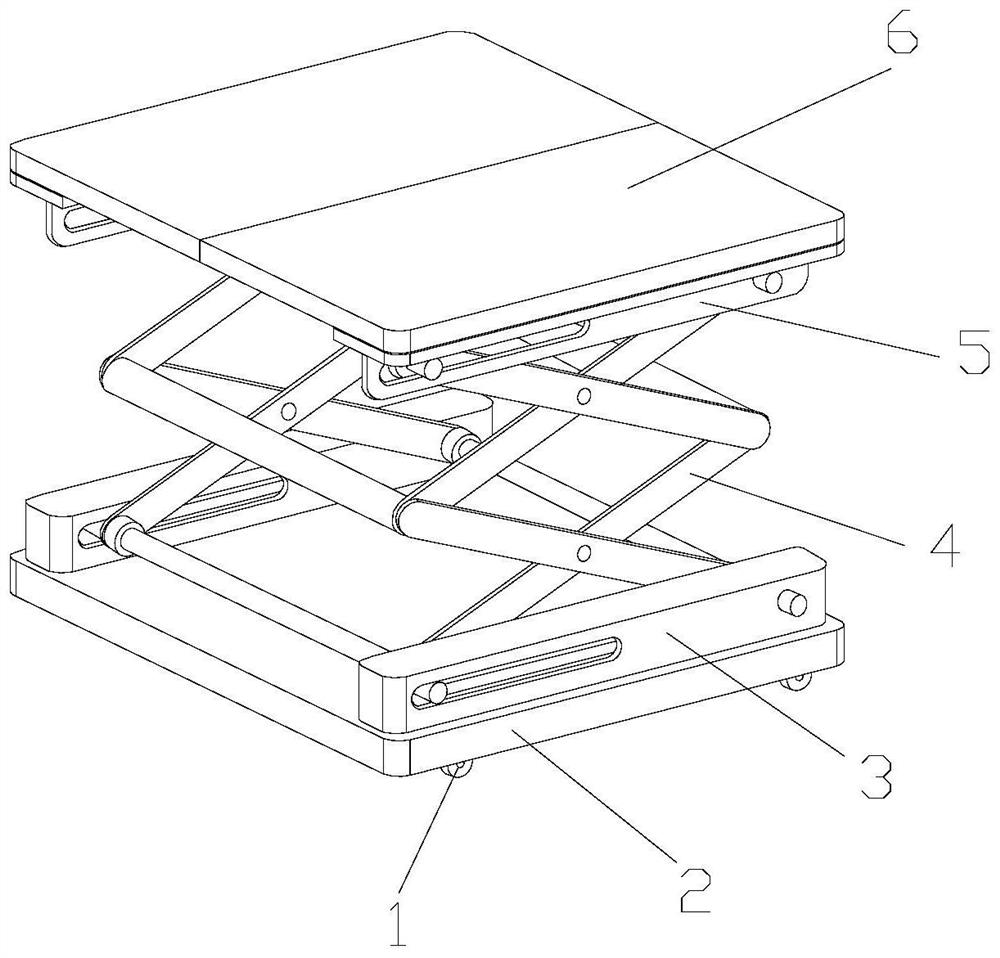
[0028] Example 1: Please refer to Figure 1-Figure 5 , the specific embodiments of the present invention are as follows:

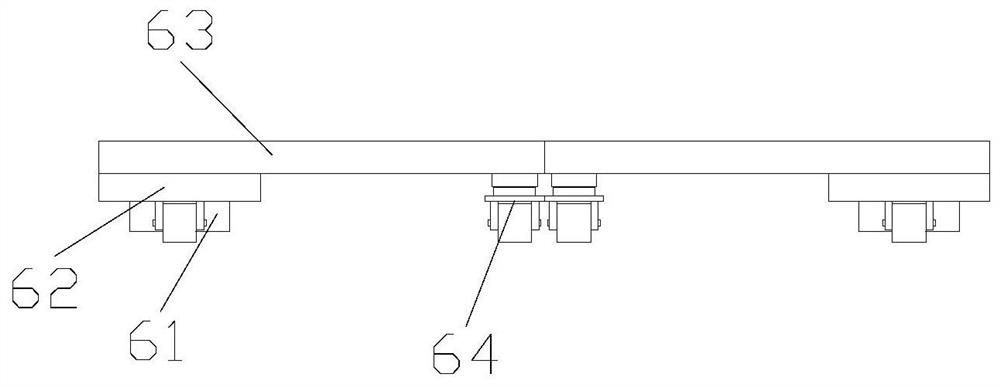
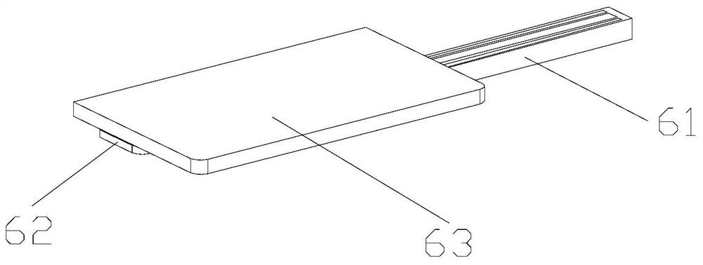
[0029] Its structure includes caster 1, bottom plate 2, driving box 3, scissors-type bracket 4, movable frame 5, lifting structure 6, said caster 1 is installed on the lower end of bottom plate 2 and adopts hinge connection, and said driving box 3 is fixedly installed on The upper end of the base plate 2, the scissor bracket 4 is embedded and installed between the drive boxes 3 and is movably connected, the movable frame 5 is hinged to the upper end of the scissor bracket 4, and the lifting structure 6 is fixedly installed on the movable frame 5 upper ends and are welded; the lifting structure 6 includes a longitudinal movable structure 61, a lateral movable structure 62, a lateral movable plate 63, and universal wheels 64, and the horizontal movable structure 62 is horizontally installed on the upper end of the longitudinal movable structure 61 and adopts...

Embodiment 2

[0035] Example 2: Please refer to Figure 1-Figure 3 , Figure 6-Figure 8 , the specific embodiments of the present invention are as follows:

[0036] Its structure includes caster 1, bottom plate 2, driving box 3, scissors-type bracket 4, movable frame 5, lifting structure 6, said caster 1 is installed on the lower end of bottom plate 2 and adopts hinge connection, and said driving box 3 is fixedly installed on The upper end of the base plate 2, the scissor bracket 4 is embedded and installed between the drive boxes 3 and is movably connected, the movable frame 5 is hinged to the upper end of the scissor bracket 4, and the lifting structure 6 is fixedly installed on the movable frame 5 upper ends and are welded; the lifting structure 6 includes a longitudinal movable structure 61, a lateral movable structure 62, a lateral movable plate 63, and universal wheels 64, and the horizontal movable structure 62 is horizontally installed on the upper end of the longitudinal movable s...


PUM


Abstract

The invention discloses an intelligent power equipment installation and lifting device, the structure of which comprises casters, a bottom plate, a drive box, a scissor bracket, a movable frame, and a lifting structure. , the scissor-type bracket is embedded and installed between the drive boxes, the movable frame is hinged to the upper end of the scissor-type bracket, and the lifting structure is fixedly installed on the upper end of the movable frame. The lifting structure includes a longitudinal movable structure, a lateral movable structure, a lateral movable plate, Universal wheels, the horizontal movable structure is horizontally installed on the upper end of the longitudinal movable structure, and the lateral movable plate is fixedly installed on the upper end of the horizontal movable structure. The expenditure of manpower makes the installation more convenient; a horizontal movable structure is set at the lower end of the horizontal moving plate, which can better adapt to the power equipment of different widths, thereby reducing the working intensity and facilitating the lifting installation of the power equipment.

Description

technical field [0001] The invention belongs to the field of electric power, and in particular relates to an intelligent power equipment installation lifting device. Background technique [0002] Power equipment is mainly used in the power system. In the process of power transmission, various power equipment is required to coordinate and control transmission to ensure the safe transmission of power. Before power transmission, it is necessary to install and connect power equipment. To carry out work, and the current power equipment is erected at a high place, requiring many people to lift up and install it, which consumes more manpower, so it is necessary to install a lifting device for intelligent power equipment to lift and install the equipment, but the existing technology There are following deficiencies: [0003] Since the lifting device is usually flat, it is necessary to carry the electric equipment on the flat for lifting, and when the electric equipment needs to be ...

Claims


Application Information

Patent Timeline
Patent Type & Authority Patents(China)
IPC IPC(8): B66F7/08B66F7/28
CPCB66F7/0666B66F7/08B66F7/28
Inventor 陈魏彬
Owner 中惺有限公司
Why Eureka
Try Eureka