
Connection structure of hospital window opening and construction method thereof

A technology of connecting structure and construction method, applied in the direction of door, joint fastening/covering, base frame, etc. to prevent harmful radiation, can solve the problems of reducing radiation protection effect, cracks in window sub-frame 2 and wall 1, etc. Achieve the effect of improving radiation resistance and sealing strength, improving connection strength, and enhancing connection strength

Active Publication Date: 2020-05-15
浙江绿境环境工程有限公司
View PDF6 Cites 2 Cited by
  • Summary
  • Abstract
  • Description
  • Claims
  • Application Information

AI Technical Summary

Problems solved by technology

When the temperature of the external environment changes, the temperature stress generated inside different structures is different, so that the temperature deformation of the window sub-frame 2 and the wall 1 is different, which will cause cracks between the window sub-frame 2 and the wall 1, reducing the Anti-radiation effect

Method used


Image

  • Connection structure of hospital window opening and construction method thereof
  • Connection structure of hospital window opening and construction method thereof
  • Connection structure of hospital window opening and construction method thereof

Examples


Embodiment 1

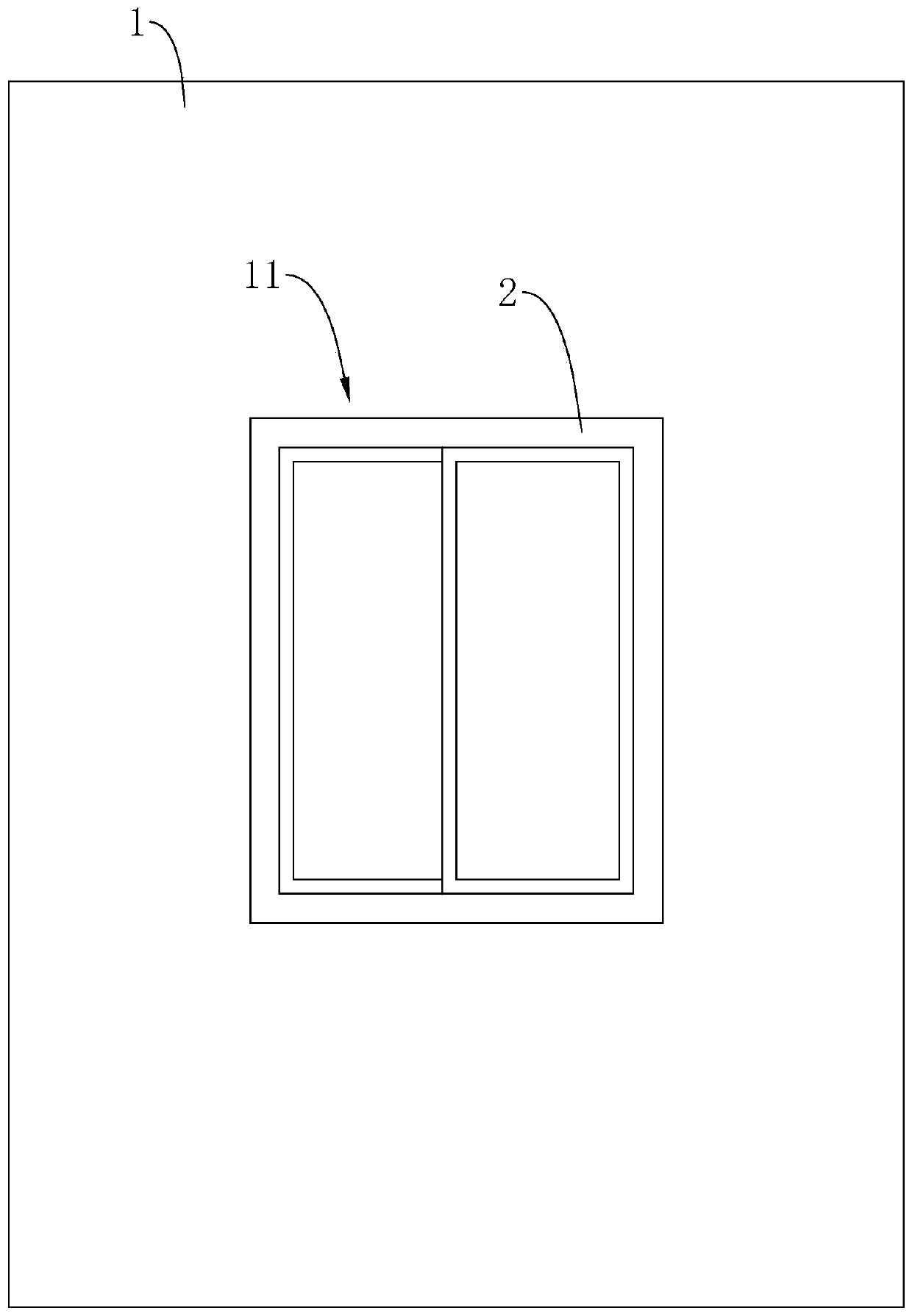
[0046] refer to figure 1 , is the construction method of the connection structure of a kind of hospital window hole disclosed by the present invention, comprises the following steps:

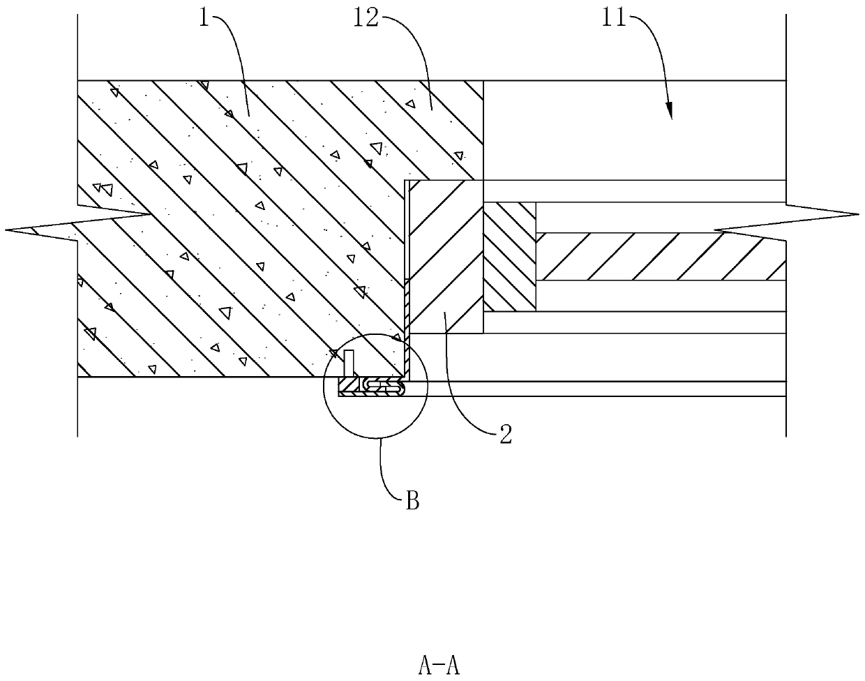
[0047] S1, laying concrete on the inner wall of the window hole 11 close to the outside, and forming a limit frame 12 after the concrete is solidified. The limit frame 12 facing the outdoor side is flush with the wall 1 facing the outdoor side, and the limit frame 12 is located in the middle of the inner wall of the window opening 11 on the indoor side. And the bounding box 12 (see image 3 ) and the vertical distance between the inner wall of the window opening 11 and the vertical distance between the inner wall of the window sub-frame 2 and the inner wall of the window opening 11 are the same.

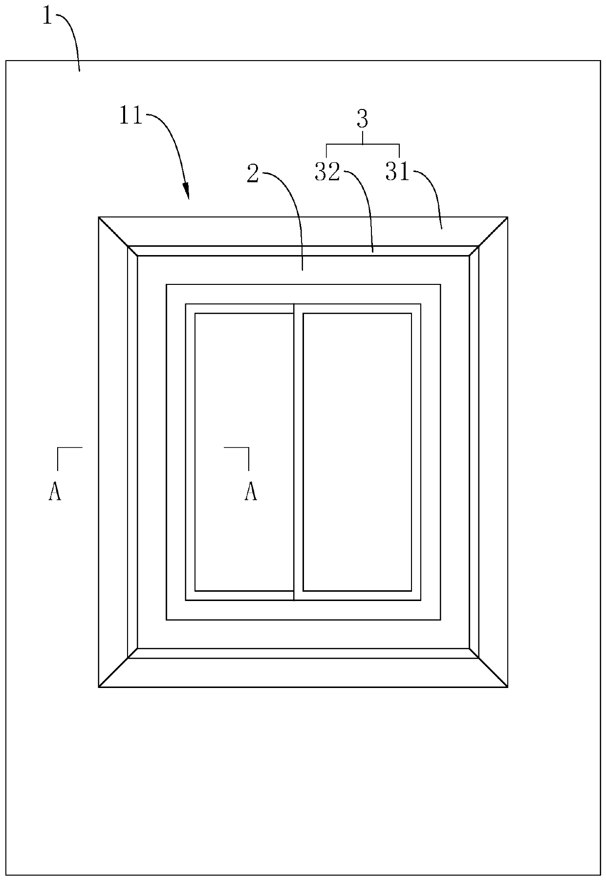
[0048] S2, combined figure 2 and image 3 1. Push the window sub-frame 2 from the window hole 11 toward the indoor side into the inside of the window hole 11 until the side wall of the window sub-f...

Embodiment 2

[0054] refer to Figure 5 , is a construction method of a connection structure of a hospital window opening disclosed in the present invention, and the only difference from Embodiment 1 is that S3 is different.

[0055] S3, combined Figure 6 and Figure 7 , Prepare eight lead plates, four of which are used as fixed plates 31 and the other four are used as movable plates 32. A fixed plate 31 and a movable plate 32 are combined to form an anti-deformation structure 3 , that is, four sets of anti-deformation structures 3 are arranged on the outer edge of the window sub-frame 2 . Each group of anti-deformation structures 3 is set corresponding to the side length of the window sub-frame 2 .

[0056] One side of the bent fixing plate 31 forms a U-shaped fixing and limiting hook 311 . Cut the two ends of the fixing plate 31 to form two symmetrical 45-degree slopes, so that the angle between the slopes and the side of the fixing plate 31 away from the fixing limit hook 311 is 135...


PUM


Abstract

The invention relates to a connection structure of a hospital window opening and a construction method thereof. The connection structure of the hospital window opening comprises the window opening arranged in a wall and an auxiliary window frame arranged inside the window opening; an anti-deformation structure is additionally arranged between the auxiliary window frame and the wall and comprises amovable plate fixed on the auxiliary window frame and a fixed plate fixed on the wall; one sides, close to each other, of the fixed plate and the movable plate are overlapped with each other, and theoverlapped parts of the fixed plate and the movable plate are parallel to the wall; and the fixed plate and the movable plate are lead plates. Due to the fact that the anti-deformation structure is arranged between the auxiliary window frame and the wall, the anti-radiation strength of the connection position of the auxiliary window frame and the wall is enhanced.

Description

technical field [0001] The invention relates to the technical field of window opening construction in a hospital radiation protection room, in particular to a connection structure of a hospital window opening and a construction method thereof. Background technique [0002] Some rooms in the hospital are used for radiation therapy such as CT, and these rooms need to be protected from radiation. Usually, the most important structure for indoor radiation protection is the lead plate. However, since windows need to be installed in the room, the radiation protection of the windows also needs to be designed. Under normal circumstances, the window sub-frame and window frame are lined with protective lead plates to achieve the purpose of radiation protection. [0003] However, refer to Figure 8 , The window sub-frame 2 is directly installed in the window hole 11 of the body of wall 1, and then the window frame 6 with glass is installed on the window sub-frame 2. The wall body 1 ...

Claims


Application Information

Patent Timeline
Patent Type & Authority Applications(China)
IPC IPC(8): E06B1/02E06B1/60E06B1/68E06B5/18
CPCE06B1/02E06B1/60E06B1/68E06B5/18
Inventor 何涛涛张芳刘雪王沈洋程超锋马炜杰周桂萍施高风
Owner 浙江绿境环境工程有限公司
Features
  • Generate Ideas
  • Intellectual Property
  • Life Sciences
  • Materials
  • Tech Scout
  • Unparalleled Data Quality
  • Higher Quality Content
  • 60% Fewer Hallucinations
Learn More