Take-up control box

A control box and box body technology, which is applied in the direction of the flexible lead device, coupling device, base/shell, etc., can solve the problem that the control box on the cable cannot automatically take up the wire, so as to avoid the electrification of the box body and meet the rotating conductive assembly , The effect of shortening the take-up time

Active Publication Date: 2022-03-08
CHINA AVIATION OPTICAL-ELECTRICAL TECH CO LTD
View PDF4 Cites 0 Cited by
  • Summary
  • Abstract
  • Description
  • Claims
  • Application Information

AI Technical Summary

Problems solved by technology

[0005] The purpose of the present invention is to provide a wire take-up control box, which is used to solve the technical problem that the cable control box applied to the charging device cannot automatically take up the wire in the prior art

Method used


Image

  • Take-up control box
  • Take-up control box
  • Take-up control box

Examples


specific Embodiment 1

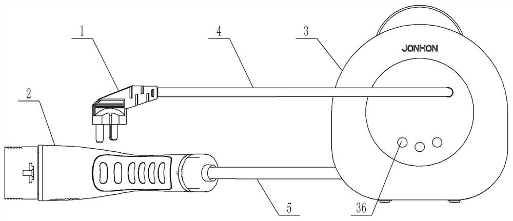
[0056] Such as figure 1 As shown, the take-up control box is used in the mode 2 charging device. According to the national standard GB / T1847.1-2015, the charging gun is divided into four categories, including the mode 2 charging gun. The mode 2 charging gun is a portable charging gun, which can be used for For home charging, the mode 2 charging device here refers to the charging device using the mode 2 charging gun.

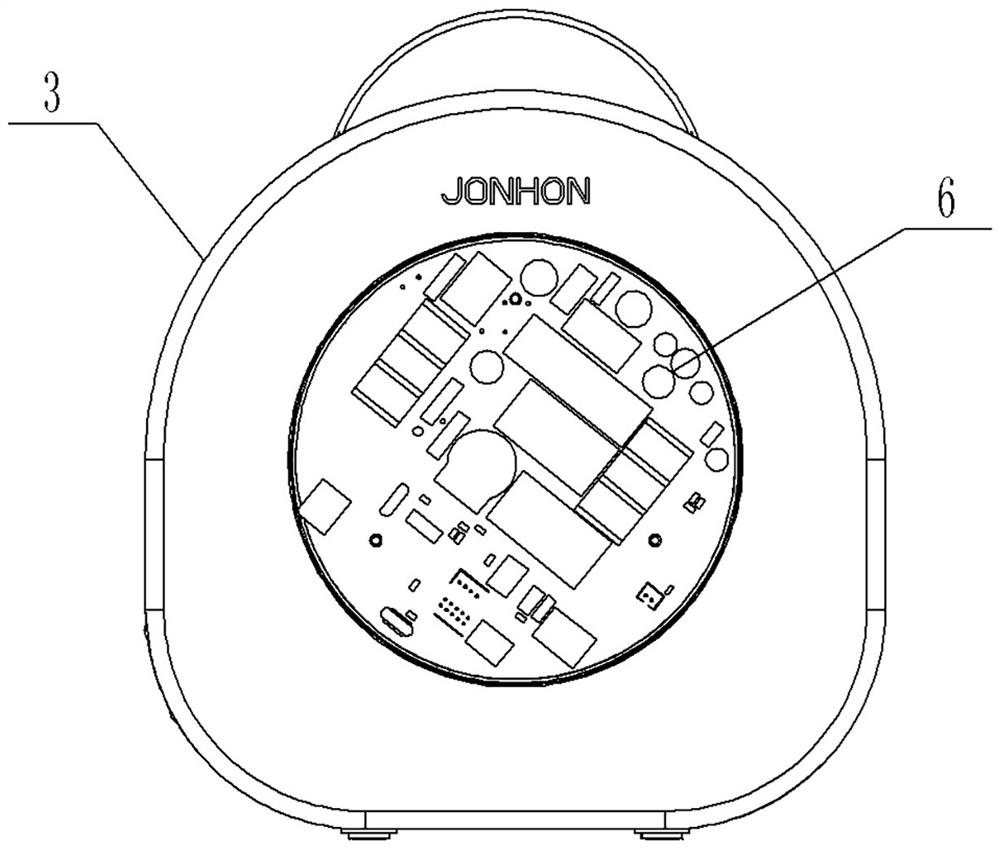
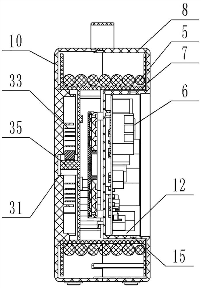
[0057] Such as figure 2 and image 3 As shown, the take-up control box 3 includes a box body and a circuit board 6 fixed in the box body, and also includes a turntable 7 rotatably assembled in the box body, and the turntable 7 is used to wind the cable 5 for passing the cable 5 and The charging gun 2 is conductively connected, and the retractable operation of the cable 5 can be realized through the circumferential rotation of the turntable 7 .

[0058] Specifically, the box body includes a box body, and the box body includes a front shell 8 and a rear shell 1...

specific Embodiment 2

[0085] It differs from Example 1 in that:

[0086] There are no ratchet segments and pawls in the locking mechanism. The locking mechanism includes a compression block arranged on the box body. When the cable is unwound to the required length, the compression block is pushed, and under the action of the compression block , the cable can be locked and pressed on the turntable, and the pressing block can be pushed in the opposite direction to unlock the cable. Under the driving action of the take-up elastic member, the automatic take-up of the take-up control box can be realized. In this embodiment, the take-up and release operation of the take-up control box can be completed by one person, that is, the operator operates at the position of the take-up control box. Locking; the take-up and release operation of the take-up control box in this embodiment can also be completed by two people.

specific Embodiment 3

[0088] It differs from Example 1 in that:

[0089]There is no groove structure on the front shell, and an opening is set at the bottom of the barrel of the front shell. A radial flange is set on the radial flange, bolt holes are set on the radial flange to form a flange plate, and the box body insulator is fixed on the radial flange with fastening bolts. At this time, the box body insulator needs to be sealed and assembled on the corresponding On the radial flange, the sealing arrangement of the circuit board accommodating cavity is realized.

[0090] In the above separation method, the circuit board accommodation cavity is surrounded by the box body and the box body insulator, and the box body insulator forms part of the cavity wall of the transition structure accommodation cavity, and the conductive ring piece, that is, the circuit board transfer terminal is located in the circuit board accommodation cavity , the inner wire drawn from the circuit board can be directly conne...


PUM


Abstract

The invention relates to a wire take-up control box. The take-up control box includes a box body, a circuit board and a turntable for winding cables. The turntable is provided with a turntable conductive transfer structure for external cables, and the box body is provided with a box body that is electrically connected to the circuit board and the turntable conductive transfer structure. Conductive transfer structure, there is also a take-up elastic part in the box body, which is used to deform when the turntable rotates in the forward direction to store the potential energy, and releases the potential energy to rotate the take-up when the turntable is turned in the reverse direction. Locking mechanism that locks the turntable and / or cable when the line is in place, and unlocks when the line is taken up. The wire take-up control box of the present invention can drive the turntable to reversely rotate and automatically take up the wire through the potential energy in the take-up elastic member, and the cable for automatic take-up is wound on the turntable, which does not occupy the space outside the box and can shorten the take-up time. Save labor and improve customer satisfaction.

Description

technical field [0001] The invention relates to a wire take-up control box. Background technique [0002] At present, home charging of electric vehicles mostly adopts AC charging, and its charging device includes a cable control box, a charging plug for connecting to a power supply, and a charging gun connected to an electric vehicle. [0003] The invention patent application document with the application publication number CN109038107A discloses a locking and unlocking control device, a plug, a socket, a cable, a component and a charging device. The charging device includes a control box on the cable, and one end of the control box on the cable is The cable is connected to the plug, and the other end is connected to the power input end of the charging gun, so that when the charging device is in working condition, the rechargeable battery of the electric vehicle can be charged through the muzzle of the charging gun. [0004] When the above-mentioned charging device is in us...

Claims


Application Information

Patent Timeline
Patent Type & Authority Patents(China)
IPC IPC(8): H01R13/72H01R13/502H01R13/52
CPCH01R13/72H01R13/502H01R13/52
Inventor 薛玉钢刘君夏全飞张海冯朋帅
Owner CHINA AVIATION OPTICAL-ELECTRICAL TECH CO LTD
Why Eureka
Try Eureka