Clean energy remote real-time centralized monitoring system

A centralized monitoring, clean energy technology, applied in system integration technology, information technology support system, electrical components, etc., can solve problems such as low voltage qualification rate, increased network loss, data modification, etc., to improve voltage qualification rate and improve control. performance, the effect of reducing voltage fluctuations

Pending Publication Date: 2020-05-15
河北建研节能设备有限公司
View PDF4 Cites 1 Cited by
  • Summary
  • Abstract
  • Description
  • Claims
  • Application Information

AI Technical Summary

Problems solved by technology

[0003] Since the installation locations of wind farms / photovoltaic power stations are far away from the load center, they are generally connected to the system through 220kV or 500kV ultra-high voltage lines. The control of reactive power, voltage and network loss is more difficult
[0004] At present, the AVC and AGC control of the photovoltaic power station of the wind farm in the power grid under the jurisdiction is being implemented, and the operating system is formed through the combination of AVC and AGC. However, the control effect of the existing system is not ideal, the voltage fluctuates frequently, and the voltage qualification rate is low. Some systems have low security performance, which is easy to cause data changes and leaks, increasing the probability of network loss, and the existing system is complex in operation and cannot adapt to various complex structures. For this reason, we propose a remote real-time concentration of clean energy monitoring system to solve the above problems

Method used


Image

  • Clean energy remote real-time centralized monitoring system
  • Clean energy remote real-time centralized monitoring system
  • Clean energy remote real-time centralized monitoring system

Examples


Embodiment Construction

[0019] The technical solutions in the embodiments of the present invention will be clearly and completely described below in conjunction with the accompanying drawings in the embodiments of the present invention. Obviously, the described embodiments are only a part of the embodiments of the present invention, rather than all the embodiments.

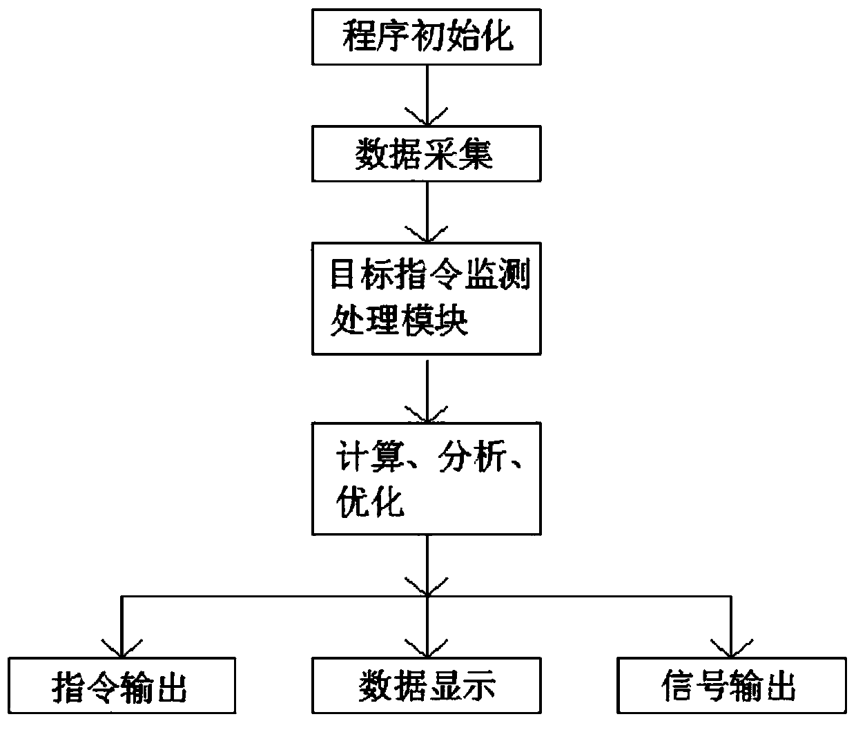
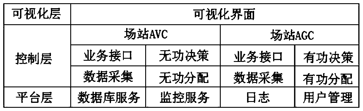
[0020] Reference Figure 1-2 , A clean energy remote real-time centralized monitoring system, including a visualization layer, a control layer, and a platform layer. The visualization layer includes a visualization interface. The control layer includes site AVC and site AGC. Site AVC includes business interface, reactive power decision-making, and data Collection and reactive power distribution. Station AGC includes business interface, active power decision-making, data collection and active power distribution. The platform layer includes database services, monitoring services, logs and user management.

[0021] In the present invention, the ...


PUM


Abstract

The invention discloses a clean energy remote real-time centralized monitoring system. The system comprises a visualization layer, a control layer and a platform layer, the visualization layer comprises a visualization interface, and the control layer comprises a field station AVC and a field station AGC. The field station AVC comprises the service, reactive power decision, data acquisition and reactive power distribution interfaces, and the field station AGC comprises the service, active power decision, data acquisition and active power distribution interfaces. According to the invention, thetarget can be controlled in various modes, by utilizing a perfect distribution algorithm and the protection measures, the system is adaptable to various complex structures, and the redundant design of all equipment and channels is realized. Meanwhile, with the multiple locking and limiting functions, the false adjustment, frequent adjustment and oscillation adjustment can be prevented effectively, and by utilizing the identity verification, the programs and parameters can be prevented from being inadvertent mistakenly modified, the operation is simple, the control performance is improved, thevoltage fluctuation is reduced, the voltage qualification rate is improved, and the monitoring effect is more conveniently displayed in a real-time change curve form.

Description

Technical field [0001] The invention relates to the technical field of a clean energy remote real-time centralized monitoring system, in particular to a clean energy remote real-time centralized monitoring system. Background technique [0002] As a kind of economical and clean renewable new energy, wind power / photovoltaic power generation is more and more widely used. According to relevant statistics, in 2008, my country’s newly added wind power installed capacity exceeded 6 million kilowatts, and the cumulative installed capacity reached over 12 million kilowatts. In 2009, the newly added installed capacity reached 13 million kilowatts, and the cumulative installed capacity reached over 25 million kilowatts. It is estimated that my country's annual new installed capacity will remain at 5-8 million kilowatts. [0003] Because wind farms / photovoltaic power plants are installed far away from the load center, they are generally connected to the system through 220kV or 500kV ultra-hig...

Claims


Application Information

Patent Timeline
Patent Type & Authority Applications(China)
IPC IPC(8): H02J13/00H02J3/46H02J3/38
CPCH02J13/00H02J3/46Y04S10/40Y04S10/123Y02E40/70
Inventor 彭月明田树辉黄佳郝晓忠张超强
Owner 河北建研节能设备有限公司
Why Eureka
Try Eureka