Supercharge Your Innovation With Domain-Expert AI Agents!

Fuel feed device and fuel pressure regulator

A technology of fuel supply device and fuel pressure, which is applied to liquid fuel feeders, charging systems, engine components, etc., and can solve the problems of increased battery burden, increased current consumption, and high operating noise of the fuel pump 4, etc.

Inactive Publication Date: 2003-06-18
MITSUBISHI ELECTRIC CORP
View PDF2 Cites 0 Cited by
  • Summary
  • Abstract
  • Description
  • Claims
  • Application Information

AI Technical Summary

Problems solved by technology

[0014] As mentioned above, the fuel pump 4 has nothing to do with the fuel flow rate required by the injector, and its motor is usually in full operation, so its current consumption increases and the burden on the battery mounted on the vehicle increases.
Again, since the motor of the fuel pump 4 is still rotating at a high speed when the engine is idling, etc., and the sound of the engine is small, the problem that exists is that the operating noise of the fuel pump 4 is too large.

Method used


Image

  • Fuel feed device and fuel pressure regulator
  • Fuel feed device and fuel pressure regulator
  • Fuel feed device and fuel pressure regulator

Examples


Embodiment Construction

[0026] specific implementation

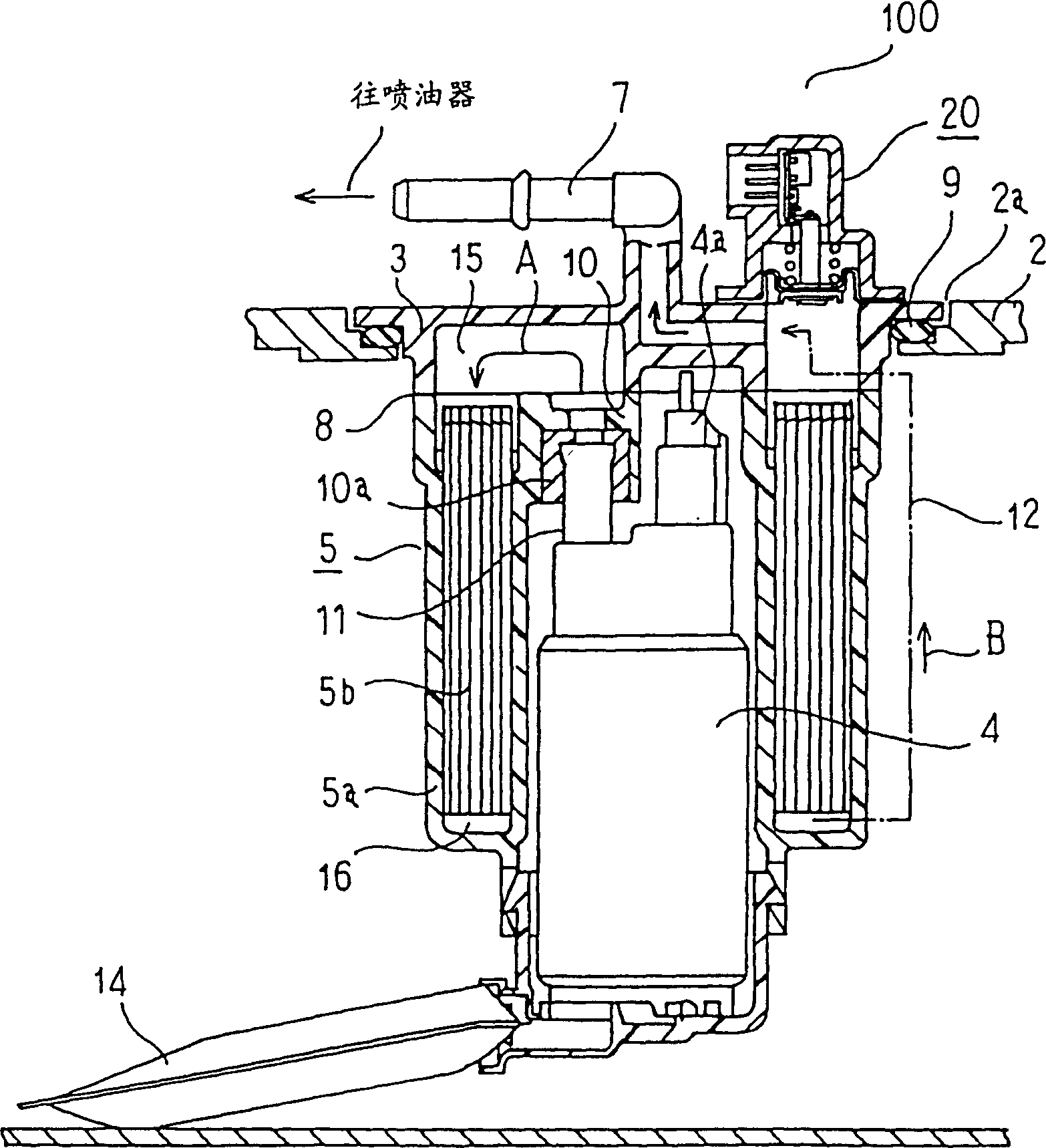
[0027] figure 1 It is a side sectional view of the fuel supply device in one embodiment of the present invention. In the figure, 100 is a fuel supply device, and a cover 3, a fuel pump 4, a fuel filter 5, a fuel injection pipe 7, a coarse filter 14, a fuel pressure regulator 20, and a fuel level gauge (not shown) are integrally formed . And it hangs on the opening part 2a of the fuel tank 2 formed by metal or resin.

[0028] The fuel filter 5 is composed of a support member 5a made of conductive resin and a filter element 5b housed inside, and the cap 3 and the boundary portion 8 are welded in a liquid-tight manner. The fuel pump 4 is supported at the central portion of the support member 5a, and a fuel level gauge (not shown) is supported at the lower end thereof. A sealing gasket 9 for airtight support is installed between the cover 3 and the fuel tank 2 .

[0029] An inlet portion 10 serving as a fuel inlet of the fuel filter 5 is prov...


PUM


Abstract

A fuel pressure regulator which stores a fuel pressure detecting part formed by a diaphragm part for detecting the pressure of fuel delivered from a fuel pump and a current control part for analogically controlling a current flowing to the fuel pump by a signal from the fuel pressure detecting part and which is provided on the upper surface of a cover part of a fuel feed device to be load in an opening of a fuel tank, wherein the fuel pump is operated so that it delivers fuel according to a flow rate requirement of an injector installed on an engine, and thus the operating current of the fuel pump is reduced and also the operating noise is reduced.

Description

technical field [0001] The present invention relates to a fuel (fuel) supply device that is built in a fuel tank such as an automobile, pressurizes an injector that injects fuel into an engine, and supplies fuel. Background technique [0002] Figure 5 It is a side sectional view of a conventional fuel supply device disclosed in International Publication No. WO96 / 23967. [0003] In the figure, 1 is a fuel (oil) supply device, which consists of a cover 3, a fuel (fuel injection) pump 4, a fuel filter 5, a pressure regulator 6, a fuel injection pipe 7, a fuel level gauge not shown in the figure and an electrical The joint is integrally formed and hangs from the opening 2a of the fuel tank 2 formed of metal or resin. [0004] The fuel filter 5 is formed of a support member 5a made of conductive resin and a filter element 5b accommodated therein, and the cap 3 and the boundary portion 8 are welded in a liquid-tight manner. The support member 5 a supports the fuel pump 4 at its...

Claims


Application Information

Patent Timeline
Patent Type & Authority Patents(China)
IPC IPC(8): F02M37/08F02M37/10
CPCF02M37/10F02M37/103F02M2037/087
Inventor 平岩胜金丸茂树
Owner MITSUBISHI ELECTRIC CORP
Features
  • R&D
  • Intellectual Property
  • Life Sciences
  • Materials
  • Tech Scout
  • Unparalleled Data Quality
  • Higher Quality Content
  • 60% Fewer Hallucinations
Learn More