Lake sludge cleaning equipment

A technology for cleaning equipment and silt, which is applied to earth movers/shovels, mechanically driven excavators/dredgers, construction, etc. It can solve the problems of fast drying speed, high cost, and single silt adsorption surface, and achieve structural Reasonable design, easy to clean, ensure comprehensive effect

Active Publication Date: 2020-05-19
宁波碧城生态科技有限公司
View PDF5 Cites 1 Cited by
  • Summary
  • Abstract
  • Description
  • Claims
  • Application Information

AI Technical Summary

Problems solved by technology

[0006] The object of the present invention is to provide a kind of lake mud cleaning equipment, to solve the above background technology, most of the existing cleaning equipments are relatively simple in structure, and the mud is cleaned by pushing the mud pump or the suction structure, and the suction structure is generally in the In a relatively static state, the adsorption surface of silt is relatively single; after the suction of silt is completed, the silt is generally transported to the shore storage equipment through the silt pump across the bank and a long pipeline, so more cleaning equipment needs to be used A variety of general-purpose mechanical equipment such as motors and suction pumps are costly; after the water in lakes and rivers is pumped out, the surface layer of some sludge dries up quickly, and the existing cleaning equipment cannot easily clean this part of the sludge, which increases the cost. Difficulty cleaning up

Method used


Image

  • Lake sludge cleaning equipment
  • Lake sludge cleaning equipment
  • Lake sludge cleaning equipment

Examples


Embodiment Construction

[0026] The following will clearly and completely describe the technical solutions in the embodiments of the present invention with reference to the accompanying drawings in the embodiments of the present invention. Obviously, the described embodiments are only some, not all, embodiments of the present invention. Based on the embodiments of the present invention, all other embodiments obtained by persons of ordinary skill in the art without making creative efforts belong to the protection scope of the present invention.

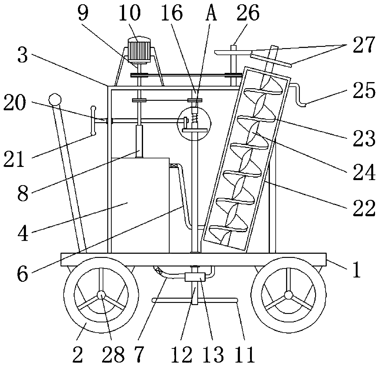
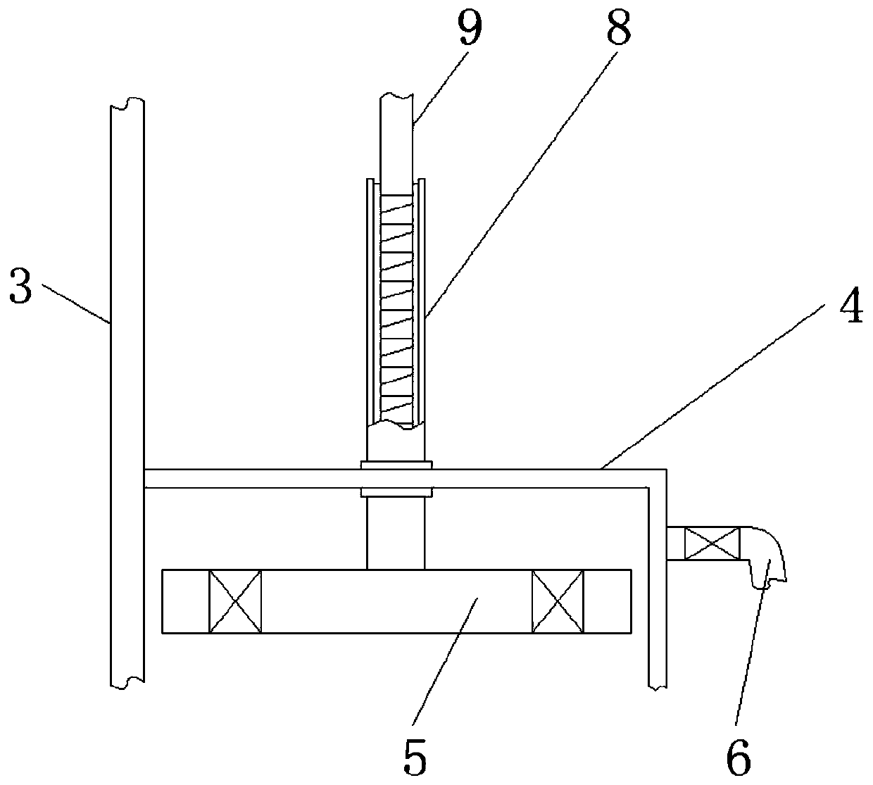
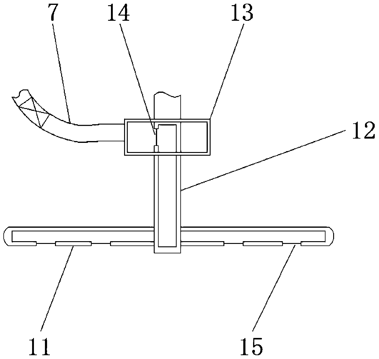
[0027] see Figure 1-6 , the present invention provides a technical solution: a lake silt cleaning equipment, including a car plate 1, a walking wheel 2, an external casing 3, a power chamber 4, a valve plate 5, a discharge pipe 6, a suction pipe 7, a vertical cylinder 8, Rotating shaft 9, motor 10, cleaning rod 11, displacement rod 12, collar 13, through hole 14, suction hole 15, control rod 16, spring 17, control board 18, cam 19, cross bar 20, handle 21, de...


PUM


Abstract

The invention discloses lake sludge cleaning equipment. The lake sludge cleaning equipment comprises a vehicle plate, walking wheels and an outer machine shell, wherein the outer machine shell is mounted on the upper end surface of the vehicle plate, the walking wheels are arranged on the sides of the vehicle plate, a power chamber is arranged inside the outer machine shell, and a cross rod is arranged on the side of a control rod; the side of the outer machine shell is connected with a conveying cylinder in a welded manner, the conveying cylinder is obliquely distributed, an auger plate is arranged inside the conveying cylinder, the auger plate is installed on a conveying shaft, and the conveying shaft and the conveying cylinder are coaxially distributed; the top end of the conveying cylinder is connected with a discharging pipe, and the side of the conveying cylinder is provided with a transmission shaft; and the walking wheels are mounted on wheel shafts, the inner ends of the wheelshafts are connected with horizontal rods, and a pressing plate is arranged below each horizontal rod. The lake sludge cleaning equipment cooperates with a manually-operated suction structure to moveup and down, sludge at different depths and in different directions can be comprehensively cleaned, and meanwhile the sludge can be conveniently discharged after cleaning.

Description

technical field [0001] The invention relates to the technical field of lake treatment, in particular to a lake sludge cleaning device. Background technique [0002] Lakes and rivers are relatively closed water storage structures. As people pay more and more attention to environmental health, the environmental governance of lakes and rivers is becoming more and more important. There are various ways of lake environmental governance. In addition to monitoring and protecting the water surface environment In addition, it is also necessary to clean up the silt at the bottom of lakes in heavily polluted areas. When cleaning small lakes and rivers, it is necessary to pump out the water first, and then use cleaning equipment to clean the bottom silt. Generally, when cleaning silt, large equipment will be used It is used in combination with small hand-push electric equipment, but the existing small cleaning equipment has the following problems in actual use: [0003] 1. Most of the ...

Claims


Application Information

Patent Timeline
Patent Type & Authority Applications(China)
IPC IPC(8): E02F5/28E02F3/88E02F3/90
CPCE02F5/28E02F3/8816E02F3/90
Inventor 不公告发明人
Owner 宁波碧城生态科技有限公司
Why Eureka
Try Eureka