A long-span variable-section beam

A variable-section beam and large-span technology, applied in the direction of girders, joists, truss beams, etc., can solve the problems of large proportion of structural self-weight, reduced beam section height, and insufficient shear bearing capacity, so as to save project cost, The force is clear and the effect of reducing the difficulty of construction

Active Publication Date: 2021-06-01
SHANDONG JIANZHU UNIV
View PDF7 Cites 0 Cited by
  • Summary
  • Abstract
  • Description
  • Claims
  • Application Information

AI Technical Summary

Problems solved by technology

However, the segmental variable cross-section beam plus slab concrete structure system has the following disadvantages: (1) due to the use of concrete structure system, the structure has a large proportion of self-weight, which is only suitable for ordinary span structures and not suitable for long-span structures; (2) the middle The beam section is rigidly connected to the beam sections on both sides, and the variable section bears not only the shear force but also a large bending moment, the structure is a statically indeterminate structure, the structural analysis is complicated, and the section height of the beam is limited. The situation is difficult to meet the design requirements. Limited by the height of the building, the equipment and pipelines often pass through the structural beams. If the opening of the beams is used, the local stress concentration at the opening will be complicated, and the complex force needs to be calculated and analyzed using the complex structural finite element method. The construction is difficult; (3) Under strong earthquake action, a plastic hinge is formed in the beam section with a small section height, and the shear bearing capacity of the concrete beam section here is insufficient, which may easily cause the overall collapse of the structure

Method used


Image

  • A long-span variable-section beam
  • A long-span variable-section beam
  • A long-span variable-section beam

Examples


Embodiment 1

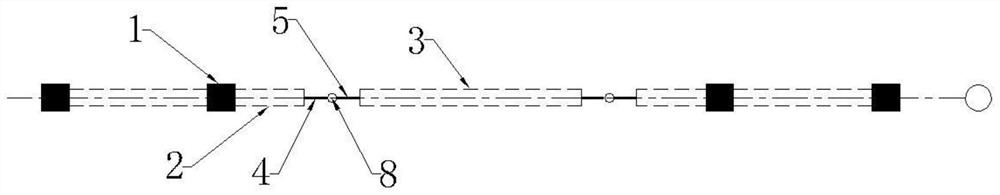
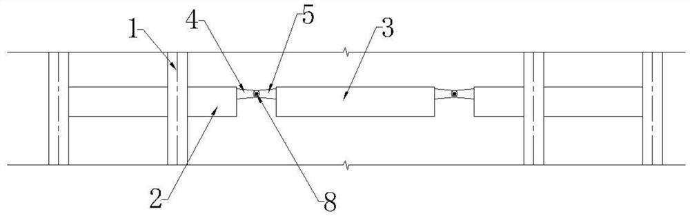
[0026] like figure 1 and figure 2 As shown, a large-span variable-section beam includes a column 1, a cantilever section 2, a simply supported section 3 and a short beam section. The cantilever section 2 is located on both sides and is fixedly connected to the column 1. The simply supported section 3 is located in the middle and its two sides The ends are respectively connected with two cantilever sections 2 through short beam sections. Cantilever section 2 and simply supported section 2 are both made of reinforced concrete. The short beam section includes the cantilever side short beam section 4 and the simply supported side short beam section 5, the cantilever side short beam section 4 and the simply supported side short beam section 5 are all shaped steel, the cantilever side short beam section 4 and the simply supported side short beam section 5 are connected by a pin shaft 8, the end of the short beam section 4 on the cantilever side extends to the inside of the cantil...

Embodiment 2

[0029] like Figure 5 and Image 6 As shown, a large-span variable-section beam includes a column 1, a cantilever section 2, a simply supported section 3 and a short beam section. The cantilever section 2 is located on both sides and is fixedly connected to the column 1. The simply supported section 3 is located in the middle and its two sides The ends are respectively connected with two cantilever sections 2 through short beam sections. Cantilever section 2 and simply supported section 2 are both made of reinforced concrete. The short beam section includes the cantilever side short beam section 4 and the simply supported side short beam section 5, the cantilever side short beam section 4 and the simply supported side short beam section 5 are all shaped steel, the cantilever side short beam section 4 and the simply supported side short beam section 5 are connected by a pin shaft 8, the end of the short beam section 4 on the cantilever side extends to the inside of the cantil...

Embodiment 3

[0034] like Figure 7 and Figure 8As shown, a large-span variable-section beam includes a column 1, a cantilever section 2, a simply supported section 3 and a short beam section. The cantilever section 2 is located on both sides and is fixedly connected to the column 1. The simply supported section 3 is located. One end of the 3 is connected to the cantilever section 2 on one side through a short beam section, and the other end of the simply supported section 3 is fixedly connected to the cantilever section 2 on the other side. Cantilever section 2 and simply supported section 2 are both made of reinforced concrete. The short beam section includes the cantilever side short beam section 4 and the simply supported side short beam section 5, the cantilever side short beam section 4 and the simply supported side short beam section 5 are all shaped steel, the cantilever side short beam section 4 and the simply supported side short beam section 5 are connected by a pin shaft 8, t...


PUM


Abstract

The invention relates to the field of building construction, in particular to a large-span variable-section beam, including a column, a cantilever section, a simply supported section and a short beam section, the cantilever section is located on both sides and fixedly connected to the column, the simply supported section is located in the middle and at least its One end is connected to the cantilever section through a short beam section. The short beam section includes a cantilever side short beam section and a simply supported side short beam section. The cantilever side short beam section and the simply supported side short beam section are hinged. The end of the cantilever side short beam section is connected to The cantilever section is fixedly connected, and the end of the simply supported side short beam section is fixedly connected to the simply supported section. The large-span variable-section beam of the present invention can effectively reduce the height of the local section, thereby increasing the height of the local use space of the building, meeting the space use requirements of the building, without increasing the height of the building due to equipment and pipelines, and saving engineering costs.

Description

technical field [0001] The invention relates to the field of building structures, in particular to a large-span variable-section beam. Background technique [0002] With the rapid development of the economy and the improvement of people's living standards, people's demand for construction products is also increasing. High-rise and super high-rise buildings such as shopping malls, hotels, office buildings, airports, railway stations, and large urban complexes many. In order to meet the requirements of building quality, local long-span structures are unavoidable. Local long-span structures mean that local structures require a larger cross-sectional height of beams. For the sake of building economy, building height control is relatively strict, and long-span spaces need to be considered comprehensively The space reserved for equipment and pipelines, architectural decoration practices, and the setting of fire shutters are generally insufficient for the cross-sectional height of...

Claims


Application Information

Patent Timeline
Patent Type & Authority Patents(China)
IPC IPC(8): E04C3/02E04B1/58E04B1/18
CPCE04B1/185E04B1/58E04B2001/5868E04C3/02
Inventor 李士彬田艳玫刘伟王东方刘明辉刘冶顾绍义李金玮杨登峰
Owner SHANDONG JIANZHU UNIV
Why Eureka
Try Eureka