Position-based multi-hydraulic cylinder coordinated control method and device for smooth output of liquid

A coordinated control, multi-hydraulic cylinder technology, used in fluid pressure actuation devices, fluid pressure actuation system components, servo motors, etc., can solve the problems of output flow and pressure pulsation, and achieve small flow and pressure pulsation, output flow The effect of stable and stable output

Active Publication Date: 2022-07-22
XINJIANG UNIVERSITY
View PDF1 Cites 0 Cited by
  • Summary
  • Abstract
  • Description
  • Claims
  • Application Information

AI Technical Summary

Problems solved by technology

[0003] The present invention provides a position-based multi-hydraulic cylinder coordinated control method and device for stably outputting liquid, which overcomes the above-mentioned deficiencies in the prior art, and can effectively solve the pulsation of output flow and pressure in the existing multi-group hydraulic cylinder control method The problem

Method used


Image

  • Position-based multi-hydraulic cylinder coordinated control method and device for smooth output of liquid
  • Position-based multi-hydraulic cylinder coordinated control method and device for smooth output of liquid
  • Position-based multi-hydraulic cylinder coordinated control method and device for smooth output of liquid

Examples


Embodiment 1

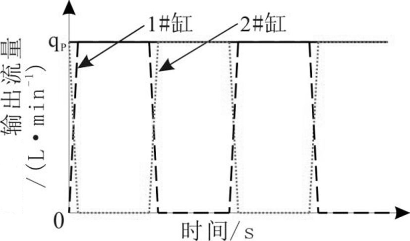
[0028] Embodiment 1: The position-based multi-hydraulic cylinder coordinated control method for smoothly outputting liquid is carried out as follows: before the n groups of hydraulic cylinders work, the strokes of the n groups of hydraulic cylinders are initialized, and the n groups of hydraulic cylinders are respectively in At the starting point of the stroke, near the end point, and at the (n-m+1) / (n-1) stroke, any group of hydraulic cylinders in the n groups of hydraulic cylinders is recorded as the mth group of hydraulic cylinders, 1≤m≤n, m, n are all natural numbers;

[0029] After the hydraulic cylinder stroke of each group of hydraulic cylinders is initialized, the hydraulic cylinder starts to work, the mth group of hydraulic cylinders is in a stop waiting state (at the starting point of the stroke), and the other groups of hydraulic cylinders move normally. When the m+1th group of hydraulic cylinders is about to reach the stroke At the end point, control the reversing ...

Embodiment 2

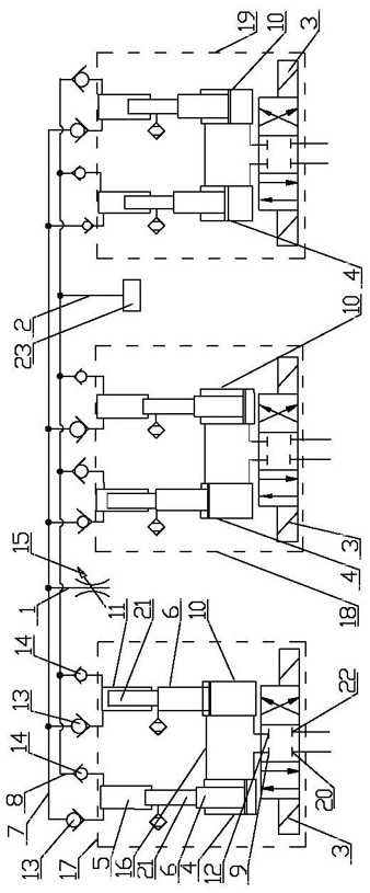
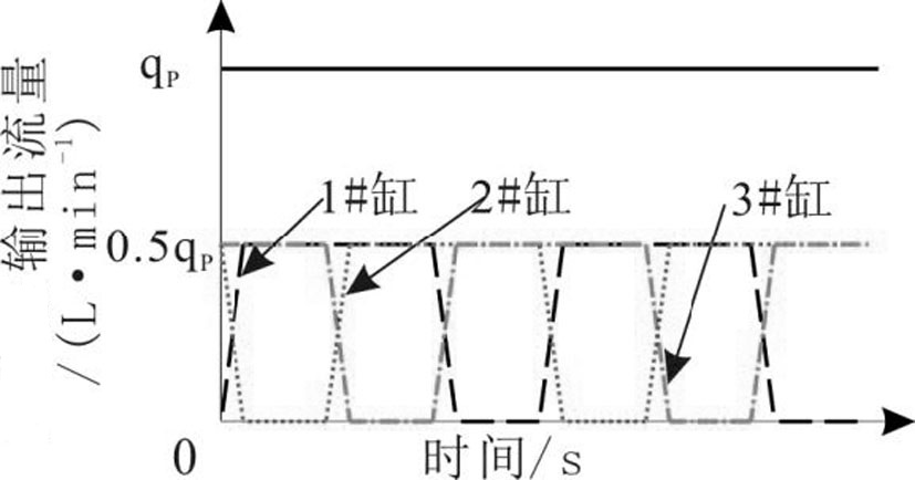
[0030] Embodiment 2: As an optimization of the above embodiment, the position-based multi-hydraulic cylinder coordinated control method for smoothly outputting liquid is carried out as follows: when n is three, before the three groups of hydraulic cylinders work, firstly control the three groups of hydraulic cylinders. The piston position of the hydraulic cylinder is initialized. The initial states of the three groups of hydraulic cylinders are at the starting point, middle point and end point of the stroke respectively, that is, the piston of any one of the hydraulic cylinders in group I 17 is at the starting point of the stroke, and the hydraulic cylinder in group II 18. The piston of any one of the piston cylinders is at the end of the stroke, and the piston of any one of the cylinders in the third group of hydraulic cylinders 19 is at the midpoint of the stroke, and then the three groups of hydraulic cylinders start to work,

[0031] Group II hydraulic cylinder 18 and group...

Embodiment 3

[0032] Embodiment 3: As an optimization of the above-mentioned embodiment, the difference from Embodiment 2 is that the position-based multi-hydraulic cylinder coordinated control method for smoothly outputting liquid is carried out as follows: when n is four, at four Before the group of hydraulic cylinders work, initialize the piston positions of the four groups of hydraulic cylinders. The initial states of the four groups of hydraulic cylinders are at the starting point, end point, 2 / 3 stroke, and 1 / 3 stroke, respectively, that is, group I. The piston of any piston cylinder in hydraulic cylinder 17 is at the starting point of the stroke, the piston of any piston cylinder in group II hydraulic cylinder 18 is at the end of the stroke, and the piston of any piston cylinder in group III hydraulic cylinder 19 is at 2 / 3 stroke. , the piston of any one of the cylinders in the IV group is at 1 / 3 of the stroke, and then the four groups of hydraulic cylinders start to work,

[0033] W...


PUM


Abstract

The invention relates to the technical field of multi-group hydraulic cylinder control, and relates to a position-based multi-hydraulic cylinder coordinated control method and device for stably outputting liquid. , and then the hydraulic cylinder starts to work. By detecting the position of a group of hydraulic cylinder pistons or piston rods or plungers, it controls the reversal of another group of hydraulic cylinders to achieve orderly reversal of multiple groups of hydraulic cylinders, and the startup of the mth group of hydraulic cylinders is accelerated. The process completely overlaps with the deceleration and stop process of the m+1 group of hydraulic cylinders, and the output flow is perfectly superimposed. The invention controls the reversing valve direction of another group of hydraulic cylinders by detecting the position of the piston rod or plunger of one group of hydraulic cylinders to realize orderly reversal of multiple groups of hydraulic cylinders, stable output flow, and small flow and pressure pulsation.

Description

technical field [0001] The invention relates to the technical field of multi-group hydraulic cylinder control, and relates to a position-based multi-hydraulic cylinder coordinated control method and a special device for stably outputting liquid. Background technique [0002] For the control of multiple groups of hydraulic cylinders, the traditional control method is that a group of reversing valves controls a group of hydraulic cylinders, and the reversing processes between the cylinder groups are independent of each other and do not interfere with each other. However, when two or more groups of hydraulic cylinders are required to move in coordination, due to the inherent reversal time of each hydraulic cylinder component, the difference in the opening and closing performance of the valve group, manufacturing errors, oil pipes and water hammer in the cylinder, etc. The output flow of the push plunger cylinder (load) cannot be perfectly superimposed, causing the output flow a...

Claims


Application Information

Patent Timeline
Patent Type & Authority Patents(China)
IPC IPC(8): F15B11/20F15B13/07F15B21/00
CPCF15B11/20F15B13/07F15B21/008F15B2211/8613F15B2211/8616
Inventor 杨波司冰龙
Owner XINJIANG UNIVERSITY
Why Eureka
Try Eureka