Oscillatory flow filtering method for electronic meter at zero flow point

A meter, zero-flow technology, applied in the measurement of flow/mass flow, application of thermal effect to detect fluid flow, measurement of capacity, etc. The effect of less probability of erroneous filtering occurring

Active Publication Date: 2020-05-19
GOLDCARD HIGH TECH
View PDF10 Cites 0 Cited by
  • Summary
  • Abstract
  • Description
  • Claims
  • Application Information

AI Technical Summary

Problems solved by technology

Since the amplitude of most of the actual oscillating flow is much higher than the starting flow of the meter, and the larger the oscillating flow is, the more cumulative quantity will be generated in the same time. Therefore, in the flow measured by the cumulative quantity generated, these The oscillating flow with a larger oscillating amplitude has a larger proportion. The method of increasing the threshold of the starting flow will not only lose the advantages of the flow electronic meter in small flow measurement, but also cannot achieve the desired effect.

Method used


Image

  • Oscillatory flow filtering method for electronic meter at zero flow point
  • Oscillatory flow filtering method for electronic meter at zero flow point
  • Oscillatory flow filtering method for electronic meter at zero flow point

Examples


Embodiment Construction

[0036] The present invention will be described in detail below in conjunction with the specific embodiments shown in the drawings. However, these embodiments do not limit the present invention, and the structural, method, or functional changes made by those skilled in the art based on these embodiments are all included in the protection scope of the present invention.

[0037] The terms used in the present invention are only for the purpose of describing specific embodiments and are not intended to limit the present invention. The singular forms of "a", "said" and "the" used in the present invention and the appended claims are also intended to include plural forms, unless the context clearly indicates other meanings. It should also be understood that the term "and / or" used herein refers to and includes any or all possible combinations of one or more associated listed items.

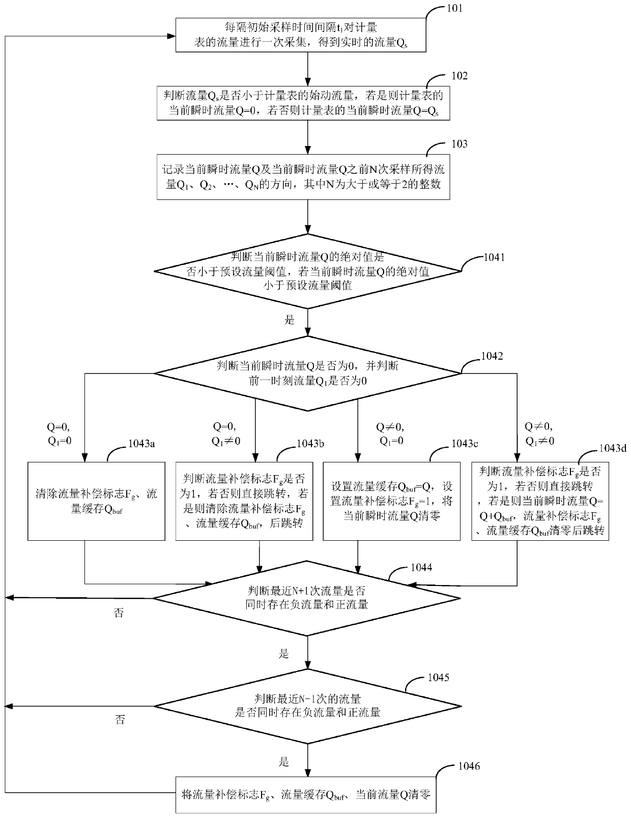
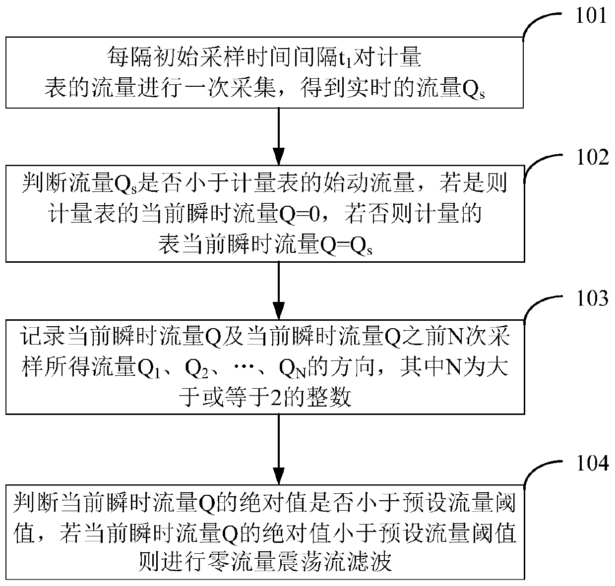
[0038] Such as figure 1 As shown, an oscillating flow filtering method for an electronic meter at the zer...


PUM


Abstract

The invention discloses an oscillatory flow filtering method for an electronic meter at a zero flow point. The method comprises the following steps: carrying out the collection of the flow of the meter at an initial sampling time interval t1, and obtaining the real-time flow Qs; judging whether the flow Qs is less than the starting flow of the meter or not, if yes, determining that the current instantaneous flow Q of the meter is equal to 0, and if not, determining that the current instantaneous flow Q of the meter is equal to Qs; recording the current instantaneous flow Q of the meter and thedirections of flow Q1, Q2,..., QN obtained by N times of sampling before Q, wherein N is an integer greater than or equal to 2; and judging whether the absolute value of the current instantaneous flow Q is less than a preset flow threshold value or not, and if the absolute value of the current instantaneous flow Q is less than the preset flow threshold value, performing zero-flow oscillation flowfiltering. The oscillation flow near the zero flow can be effectively filtered, the economic loss of the user caused by the zero flow oscillation flow is reduced, and the normal flow and the functions of the meter are not influenced.

Description

Technical field [0001] The invention relates to the technical field of metering instruments, in particular to an oscillating flow filtering method used for an electronic meter at a zero flow point. Background technique [0002] With the advancement of science and technology, the electronic metering technology of energy has developed rapidly, and the electronic meter has become famous in the meter industry. Electronic meters, including water meters, gas meters, etc., are mainly classified into ultrasonic meters and thermal meters according to the measurement mode. They measure fluid velocity through electronic sensors, and then convert them into flow through calculations. Compared with traditional model meters, electronic meters have the advantages of good repeatability, small pressure loss, long life, high accuracy, small size and no noise. [0003] The electronic meter performs well in small flow measurement, can accurately measure the flow value below the starting flow of the tr...

Claims


Application Information

Patent Timeline
Patent Type & Authority Applications(China)
IPC IPC(8): G01F1/66G01F1/68G01F15/075
CPCG01F1/66G01F1/68G01F15/075
Inventor 陈志华钭伟明
Owner GOLDCARD HIGH TECH
Why Eureka
Try Eureka