Reservoir sludge cleaning device

A technology for clearing equipment and sludge, which is applied to earth movers/shovels, mechanically driven excavators/dredgers, construction, etc. It can solve problems such as inconvenient use, cumbersome construction, and water quality impact, and achieve convenient use and overall The effect of light weight and shallow draft

Pending Publication Date: 2020-05-22
CHINA POWER CONSRTUCTION GRP GUIYANG SURVEY & DESIGN INST CO LTD
View PDF0 Cites 10 Cited by
  • Summary
  • Abstract
  • Description
  • Claims
  • Application Information

AI Technical Summary

Problems solved by technology

[0003] After the reservoir is built, when it is used for a long time, it is easy to generate silt at the bottom of the reservoir. If the silt is not cleaned, it is easy to affect the water quality. Therefore, it is necessary to regularly clean the silt in the reservoir. When cleaning, it is necessary to drain the water stored in the reservoir, and then use an excavator to clean up the sludge. The construction is more cumbersome and the cost is higher, which is not convenient for people to use.
There are also some dredging devices for ship structures. These devices are relatively large in size. Due to their deep draft, they can only be used in large rivers or shallow sea areas, and the cost is relatively high.

Method used


Image

  • Reservoir sludge cleaning device
  • Reservoir sludge cleaning device
  • Reservoir sludge cleaning device

Examples


Embodiment Construction

[0022] The present invention will be further described below in conjunction with the accompanying drawings and embodiments, but not as a basis for limiting the present invention.

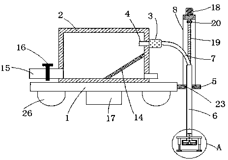
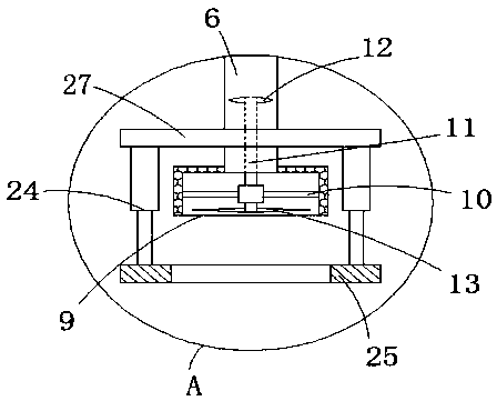
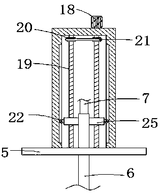
[0023] Embodiment of the present invention: a reservoir sludge cleaning device, as attached Figure 1-3 As shown, a floating plate 1 is included, a sludge tank 2 is fixedly connected to the upper end of the floating plate 1, and a sludge pump 3 is fixedly connected to the upper end of the right outer wall of the sludge tank 2, and the output end of the sludge pump 3 passes through the outlet The mud pipe 4 extends to the inside of the mud tank 2, and the right end of the floating plate 1 is fixedly connected with a support plate 5, and a round hole is arranged on the support plate 5, and a vertically arranged mud pumping pipe is movably connected in the round hole 6. The top of the mud pumping pipe 6 is connected to the input end of the sludge pump 3 through the connecting pipe 7, and a U-shaped pla...


PUM


Abstract

The invention discloses a reservoir sludge cleaning device. A sludge box is fixed to the top of a floating plate, a sludge pump is arranged at the upper end of the outer side wall of the sludge box, an output end of the sludge pump is connected to the sludge box through a sludge outlet pipe, a supporting plate is fixed to one end of the floating plate, a vertically arranged sludge suction pipe movably penetrates into a round hole of the supporting plate, the top end of the sludge suction pipe is connected to an input end of the sludge pump through a communicating pipe, a U-shaped plate is fixed to the supporting plate, a lifting mechanism is arranged on the top of the U-shaped plate and the U-shaped plate is connected to the sludge suction pipe through the lifting mechanism, a protective mesh enclosure is fixed to the bottom of the sludge suction pipe, a rotating rod is arranged in the protective mesh enclosure, the upper end of the rotating rod stretches into the sludge suction pipe,a plurality of spiral blades are fixedly connected to the upper end of the rod wall of the rotating rod, a plurality of slicers are fixedly connected to the lower end of the rod wall of the rotating rod, and a driving device is fixed to the bottom of the floating plate. It is not needed to discharge accumulated water in a reservoir thoroughly when the cleaning device is used, and the cleaning device is relatively convenient to use and relatively low in cost.

Description

technical field [0001] The invention relates to a reservoir sludge cleaning device, which belongs to the technical field of reservoir engineering equipment. Background technique [0002] After the reservoir is built, it can play the role of flood control, water storage for irrigation, water supply, power generation, fish farming, etc. Sometimes natural lakes are also called reservoirs (natural reservoirs). The scale of reservoirs is usually divided into small, medium and large according to the storage capacity. [0003] After the reservoir is built, when it is used for a long time, it is easy to generate silt at the bottom of the reservoir. If the silt is not cleaned, it is easy to affect the water quality. Therefore, it is necessary to regularly clean the silt in the reservoir. When cleaning, it is necessary to drain the water stored in the reservoir, and then use an excavator to clean up the sludge. The construction is relatively cumbersome, and the cost is high, which is ...

Claims


Application Information

Patent Timeline
Patent Type & Authority Applications(China)
IPC IPC(8): E02F3/88E02F3/90E02F3/92E02F5/28
CPCE02F3/88E02F3/8833E02F3/90E02F3/92E02F3/9256E02F3/9268E02F5/28E02F5/282
Inventor 于保宽任兵刘洪杨鹏王家信郎开松张建民李文凤
Owner CHINA POWER CONSRTUCTION GRP GUIYANG SURVEY & DESIGN INST CO LTD
Why Eureka
Try Eureka