Overflow device for improving overflow capacity and accelerating drainage of drainage valve

An overflow device and a drainage valve technology, applied in the field of bathroom, can solve the problems of reduced overflow speed, make a lot of noise, bad surrounding environment, etc., and achieve the effect of increasing drainage speed, high water flow speed and reducing noise.

Pending Publication Date: 2020-05-22
GULI (XIAMEN) TECH CO LTD
View PDF0 Cites 1 Cited by
  • Summary
  • Abstract
  • Description
  • Claims
  • Application Information

AI Technical Summary

Problems solved by technology

When the drain valve is opened, the water flows out through the drain port of the drain valve base. During normal use, since the drain port of the drain valve base communicates with the outside air through the overflow pipe channel, when draining, a negative pressure will be generated in the drain channel, and the outside world will Under the action of atmospheric pressure, the air will be mixed into the drain outlet of the drain valve base, so that the drain channel is not full of water, thereby reducing the draining speed
At the same time, the water inlet of the existing overflow pipe is generally located at the top. When an overflow occurs, a vortex is easily formed at the water inlet on the top, and the vortex brings a large amount of air into the overflow pipe, which will not only reduce the overflow speed , will also emit a lot of noise, which will have a very bad impact on the surrounding environment

Method used


Image

  • Overflow device for improving overflow capacity and accelerating drainage of drainage valve
  • Overflow device for improving overflow capacity and accelerating drainage of drainage valve
  • Overflow device for improving overflow capacity and accelerating drainage of drainage valve

Examples


Embodiment Construction

[0022] The present invention will be further described below in conjunction with the accompanying drawings and specific embodiments.

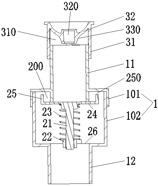
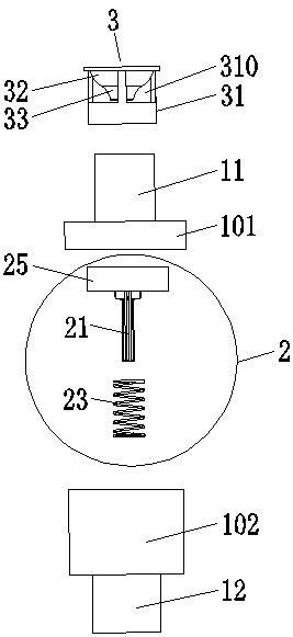
[0023] like Figure 1-3 As shown, an overflow device that improves the overflow capacity and accelerates the discharge speed of the drain valve includes a casing 1 , a check valve 2 and an overflow cap 3 . The inside of the casing 1 is provided with a cavity 10, the check valve 2 is located in the cavity 10, the top and the bottom of the casing 1 are respectively fixedly connected with a water inlet pipe 11 and a drain pipe 12 communicating with the cavity 10, the water inlet pipe 11 and the The up and down positions of the drainpipe 12 are corresponding. The housing 1 includes an upper cover 101 and a lower cover 102 that are inserted into each other. The water inlet pipe 11 and the upper cover 101 are integrally formed, and the drain pipe 12 and the lower cover 102 are integrally formed.

[0024] The check valve 2 includes a valve stem 21 ,...


PUM


Abstract

The present invention relates to an overflow device capable of improving the overflow capacity and accelerating the drainage speed of a drainage valve. The overflow device comprises a shell and a check valve, a cavity is formed in the shell, and a water inlet pipe and a drainage pipe which are communicated with the cavity are fixedly connected at the top and the bottom of the shell respectively. The check valve comprises a valve rod, a valve sleeve, an elastic body, a supporting plate and an annular water baffle, the valve sleeve is fixed to the lower portion in the cavity, and the bottom of the valve rod is installed in the valve sleeve and can move up and down. The supporting plate is fixed to the top of the valve rod, and the valve rod sleeves the elastic body and abuts against the supporting plate. The annular water baffle is fixedly arranged at the top of the supporting plate, an overflow port is formed at the top of the annular water baffle, and a water seal area is defined between the annular water baffle and the supporting plate. The bottom end of the water inlet pipe extends into the water seal area, and the bottom face of the water inlet pipe is attached to the upper surface of the supporting plate in a sealed mode. The overflow device can be independently installed to achieve the overflow function and can also be installed on the drainage valve, so that the outside air cannot enter a drainage outlet of the drainage valve, and the drainage speed of the drainage valve is increased.

Description

technical field [0001] The invention relates to the field of sanitary ware, in particular to an overflow device for improving the overflow capacity and accelerating the discharge speed of the drain valve. Background technique [0002] Existing drain valve is made of valve body, base, overflow pipe. Wherein, the valve base communicates with the overflow pipe. Under the normal water-stop state, the outside air communicates with the drain port of the drain valve base through the overflow pipe. When an overflow occurs, water flows from the overflow pipe to the drain at the base of the drain valve and into the toilet pipe. When the drain valve is opened, the water flows out through the drain port of the drain valve base. During normal use, since the drain port of the drain valve base communicates with the outside air through the overflow pipe channel, when draining, a negative pressure will be generated in the drain channel, and the outside world will Under the action of atmos...

Claims


Application Information

Patent Timeline
Patent Type & Authority Applications(China)
IPC IPC(8): E03D1/34E03D1/32E03D1/36E03D1/38
CPCE03D1/32E03D1/34E03D1/36E03D1/38
Inventor 陈雪瑜
Owner GULI (XIAMEN) TECH CO LTD
Why Eureka
Try Eureka