
Calibration method for shield tail gap measurement and shield tail gap real-time automatic measurement method and system

A shield tail gap and calibration method technology, applied in the real-time automatic measurement method and system field of shield tail gap, can solve the problem that the distance from the visual sensor to the segment is not fixed, has no operability and construction guidance, and cannot realize the shield method Refined construction and other issues to achieve the effect of convenient and effective calibration process, easy operation and convenient installation

Active Publication Date: 2020-05-22
CHINA UNIV OF MINING & TECH (BEIJING)
View PDF7 Cites 4 Cited by
  • Summary
  • Abstract
  • Description
  • Claims
  • Application Information

AI Technical Summary

Problems solved by technology

However, in the actual propulsion process of the shield machine, the forward stroke of each ring jack is not fixed, and may be larger or smaller than the ring width, so the distance from the visual sensor to the segment is not fixed, and there may be large or small deviation
[0008] The above existing measurement systems and methods are still limited to measurement, not only the measurement results are inaccurate, but also the measurement results are not processed and displayed, especially for on-site construction, they cannot be intuitively referred to by on-site construction personnel, and cannot be well understood. Combined with on-site construction, it does not have operability and construction guidance, and cannot realize the refined construction of shield tunneling method

Method used


Image

  • Calibration method for shield tail gap measurement and shield tail gap real-time automatic measurement method and system
  • Calibration method for shield tail gap measurement and shield tail gap real-time automatic measurement method and system
  • Calibration method for shield tail gap measurement and shield tail gap real-time automatic measurement method and system

Examples


Embodiment Construction

[0059] In order to make the purpose, technical solutions and advantages of the embodiments of the present invention more clear, the embodiments of the present invention will be further described in detail below in conjunction with the embodiments and the accompanying drawings. Here, the exemplary embodiments and descriptions of the present invention are used to explain the present invention, but not to limit the present invention.

[0060] In describing the present invention, it should be understood that the terms "upper", "lower", "front", "rear", "left", "right", "top", "bottom", "inner", " "Outside" and other indication orientations or positional relationships are based on the orientations or positional relationships shown in the drawings, which are only for the convenience of describing the present invention and simplifying the description, rather than indicating or implying that the referred device, component or structure must have a specific orientation, Construction or ...


PUM


Abstract

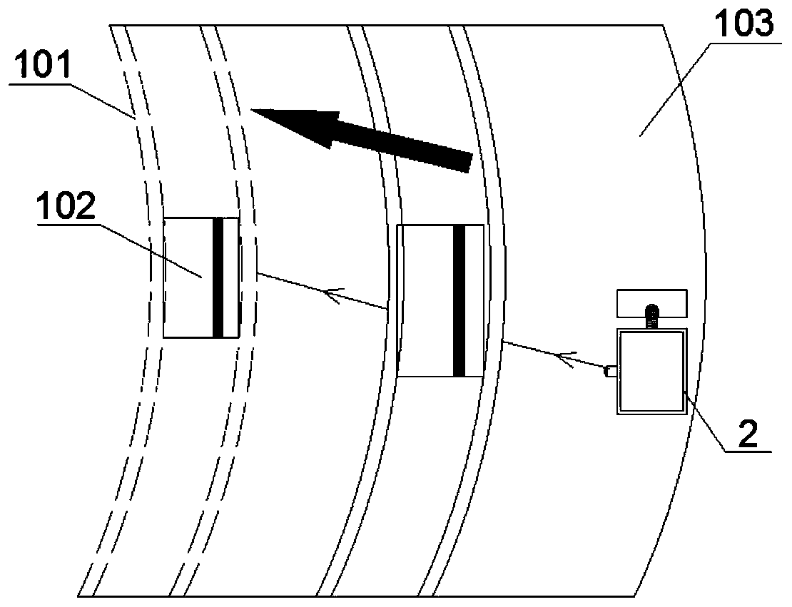
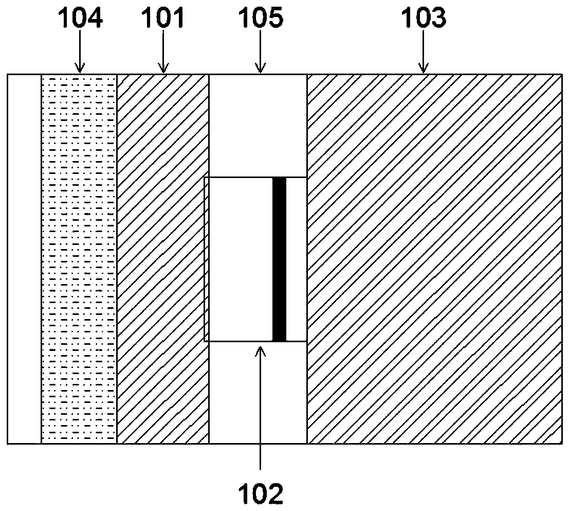
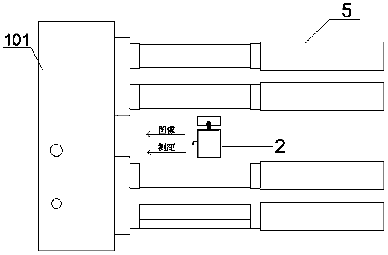
The invention provides a calibration method for shield tail gap measurement and a shield tail gap real-time automatic measurement method and system. The calibration method comprises the steps of: installing a calibration device with a characteristic graph on a segment end face; installing a data acquisition device on the inner wall of a shield shell at a certain distance from the calibration device; simulating shield tunneling, acquiring calibration device images at a plurality of positions by the data acquisition device, and acquiring distances from the data acquisition device to the calibration device at the plurality of positions; and extracting the pixel number of the images. According to the uniquely designed calibration method, the defects that in the prior art, in a shield construction environment, the recognition error is large, and the measurement result is inaccurate can be well solved, and a foundation is laid for subsequent shield measurement. The measurement method is reasonable, the measurement result is accurate, the applicability is high, the stability is high, and non-contact real-time automatic measurement is realized. And a system interface visually displays a measurement result, construction is guided through visual display, and refined construction of the shield method is achieved.

Description

technical field [0001] The invention relates to the technical field of shield tunneling, in particular to a calibration method for shield tail gap measurement, a real-time automatic measurement method and system for shield tail gap. Background technique [0002] In shield construction, the space between the inner wall of the shield shell at the tail of the shield machine and the outer diameter of the segment is the shield tail gap. At present, there are many kinds of shield tail gap measurement systems commonly used in shield tunneling. Sun Lian (Experimental Research on Shield Tail Gap Measuring Device, Modern Tunnel Technology, 2016) and others developed a SRGD shield tail gap detector with completely independent intellectual property rights, such as Figure 13 as shown, Figure 13 It is a schematic diagram of the structure of the SRGD detector. The hardware part of the SRGD detector includes: ① system control module, ② laser range finder, ③ high-precision rotary table and...

Claims


Application Information

Patent Timeline
Patent Type & Authority Applications(China)
IPC IPC(8): G01B11/14
CPCG01B11/14G01B21/042
Inventor 杨志勇江玉生孙正阳邵小康景晨钟白志强
Owner CHINA UNIV OF MINING & TECH (BEIJING)
Learn More