Flexible adjustable electrode

An electrode and flexible technology, applied in the field of flexible and adjustable electrodes, can solve the problems of cumbersome operation, inability to perform monitoring and surgical resection at the same time, and achieve the effect of high accuracy and reducing unnecessary resection

Pending Publication Date: 2020-05-26
北京华科恒生医疗科技有限公司
View PDF0 Cites 0 Cited by
  • Summary
  • Abstract
  • Description
  • Claims
  • Application Information

AI Technical Summary

Problems solved by technology

The grid-shaped cortical electrode has a dot-matrix structure, which will cover the entire tumor / epileptic focus tissue during use. After monitoring abnormal electrical signals, the grid-shaped electrode needs to be removed or uncovered, and the abnormal discharge electrode point should be removed to correspond to position, and then close the electrodes for monitoring, monitoring and surgical resection cannot be performed at the same time, and the operation is cumbersome

Method used


Image

  • Flexible adjustable electrode
  • Flexible adjustable electrode
  • Flexible adjustable electrode

Examples


Embodiment 1

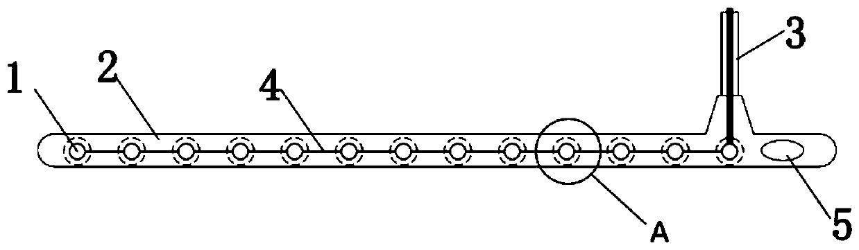
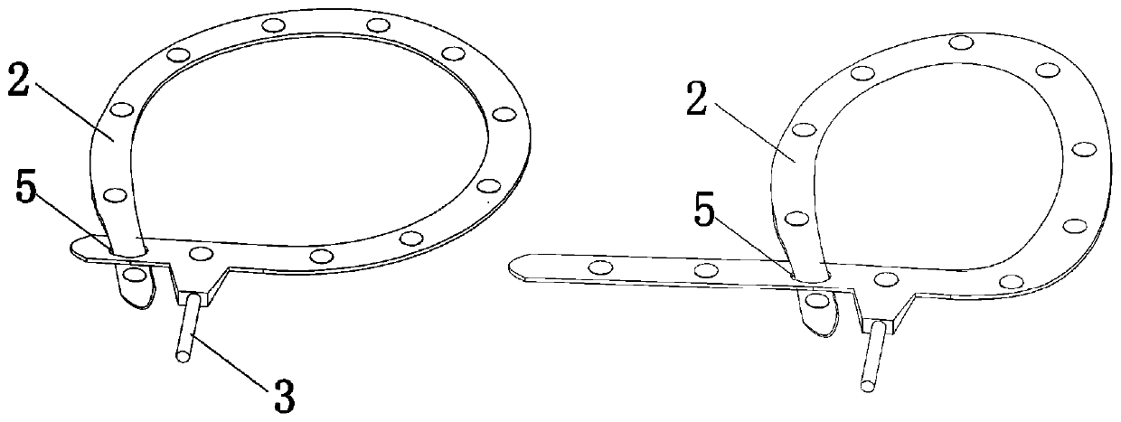
[0035] Such as figure 1 The flexible adjustable electrode shown is composed of an electrode point 1, a flexible base 2, an electrode wire sleeve 3, and an electrode guide wire 4. A further feature of this technical solution is: an oval buckle 5 is provided at the end of the flexible base 2 . Such as figure 2 As shown, the head end of the flexible and adjustable electrode can be combined with the oval buckle 5 to form any shape during use.

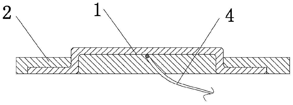
[0036] Such as image 3 As shown, the further features of this technical solution are: the upper surface of the electrode point 1 is exposed outside the flexible base 2, the back of the electrode point 1 is embedded in the flexible base 2, and the electrode point 1 is connected to the electrode guide wire 4 set in the flexible base 2 , the electrode guide wire 4 is connected to the external circuit by setting the electrode wire sleeve 3 at the end of the flexible base 2; the diameter of the exposed flexible base part is 1.5-5mm, prefera...

Embodiment 2

[0040] Such as Figure 4 The flexible adjustable electrode shown is different from Embodiment 1 in that the flexible base 2 in the middle of the two electrode points 1 is concaved inward and becomes thinner, such as Figure 5 As shown, the first end of the flexible base 2 is preferably fixed in the oval buckle 5 at the end of the flexible base 2 during use, and the head end of the flexible base 2 can also be fixed in the oval buckle 5 at any position of the flexible base 2 .

Embodiment 3

[0042] Such as Figure 6 The flexible adjustable electrode shown is composed of an electrode point 1, a flexible base 2, an electrode wire sleeve 3, and an electrode guide wire 4. A further feature of this technical solution is: the upper surface of the flexible base 2 between the two electrode points 1 is provided with a groove-shaped buckle 5 , and the lower surface of the flexible base 2 is provided with a bump 6 corresponding to the groove-shaped buckle 5 . Such as Figure 7 As shown, when in use, the lower surface of the flexible base 2 is provided with a protrusion 6 corresponding to the groove-shaped buckle 5, which can be combined with the oval buckle 5 to form any shape. Figure 8 and Figure 9 It is a partial enlarged view of two forms of the combination of the bump 6 corresponding to the groove-shaped buckle 5, one is the cylindrical groove buckle 5 on the upper surface of the flexible substrate 2 in the middle of the two electrode points 1 and the flexible substr...


PUM

PropertyMeasurementUnit
diameteraaaaaaaaaa
diameteraaaaaaaaaa

Abstract

The invention discloses a flexible adjustable electrode. The electrode comprises an electrode point, a flexible substrate, an electrode wire sleeve and an electrode guide wire, a buckle is arranged onthe flexible substrate, the flexible substrate can form any shape through the buckle, the electrode coverage area of the flexible adjustable electrode can be adjusted according to the size of a tumor/epilepsy focus, the effect of completely wrapping the focus in an irregular shape along the edge of the focus can be achieved, the purpose of 360 DEG monitoring is achieved, and the electrode has high practical clinical value due to the advantage.

Description

technical field [0001] The invention relates to a flexible adjustable electrode, in particular to an intracranial cortical electrode capable of real-time monitoring of brain waves. Background technique [0002] Many surrounding tissues of brain tumors will evolve into secondary epileptic tissues. During surgical resection of such tumors, it is necessary to remove all surrounding epileptogenic tissues as much as possible, otherwise patients will still have epileptic seizures after surgery, which will affect their quality of life. In addition, in the lesion resection operation of many patients with simple epilepsy, continuous intraoperative monitoring of whether there is abnormal discharge can enable the doctor to judge more clearly whether the lesion has been completely resected and whether the epilepsy-like discharge has been eliminated. [0003] In the above surgery, the doctor will use the intracranial cortical electrodes to monitor the brain waves in real time. Monitor f...

Claims


Application Information

Patent Timeline
Patent Type & Authority Applications(China)
IPC IPC(8): A61B5/0478
CPCA61B5/6868A61B2562/0209A61B5/291
Inventor 陈晗青李凯旺龙新云陈逍遥
Owner 北京华科恒生医疗科技有限公司
Why Eureka
Try Eureka