Pulsator washing machine and control method
A pulsator washing machine and pulsator technology, applied in the field of washing machines, can solve the problems of uneven washing effect, uneven distribution of washing liquid, and difficulty in infiltration, etc., and achieve the effects of short stroke, enhanced washing effect, and high spraying force.
- Summary
- Abstract
- Description
- Claims
- Application Information
AI Technical Summary
Problems solved by technology
Method used
Image

Examples
Embodiment 1
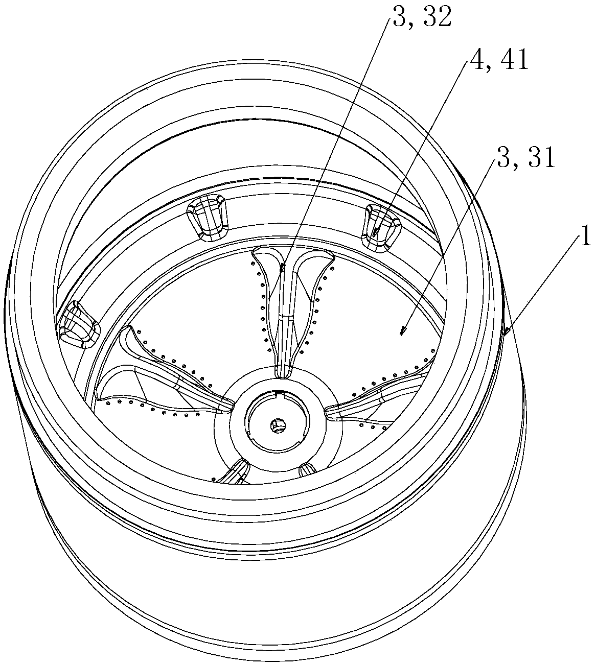
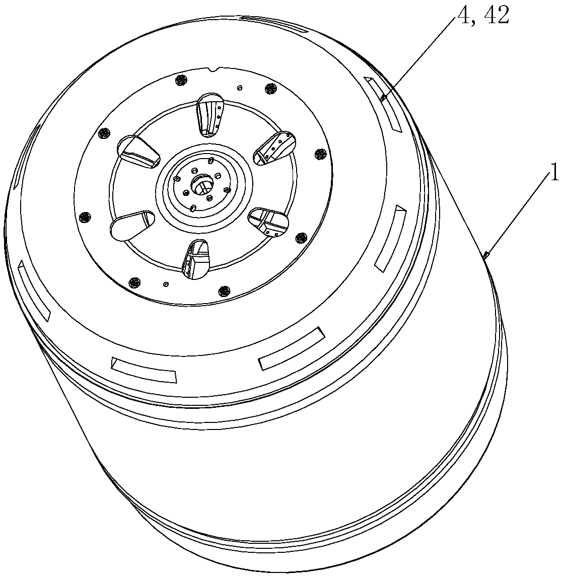
[0045] Such as Figure 1-4As shown, the present embodiment provides a pulsator washing machine, including an inner tub 1, the inner tub 1 includes an inner tub bottom 2, and a pulsator 3 is arranged in the inner tub bottom 2, and the inner tub 1 is a water-filled tub during washing / rinsing, and the inner tub 1 There is a circulating water channel 200 on the outer wall of the inner barrel, and the two ends of the circulating water channel 200 are respectively connected with the bottom 2 of the inner barrel and the upper part of the inner barrel 1. When the pulsator 3 rotates, the water flow at the bottom is pushed into the circulating water channel 200 and climbs upwards, and is sprayed into the inner barrel 1 to form Circulating water flow.
[0046] In the existing ordinary pulsator washing machine, in order to increase the effect of water circulation, the way of setting water channels on the inner wall of the inner tub 1 is adopted, which will not only reduce the effective ac...
Embodiment 2
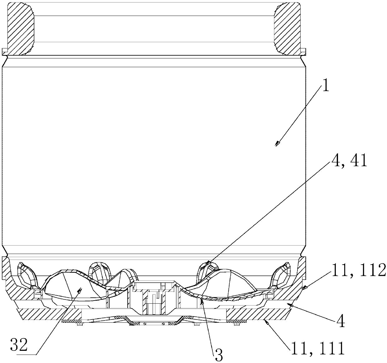
[0069] Such as Figure 1-4 As shown, this embodiment is a further limitation of Embodiment 1. The inner barrel bottom 11 of this embodiment includes a bottom wall 111 and a side wall 112 connected to each other. The side wall 112 is arranged on the outer peripheral edge of the bottom wall 111. The bottom wall 111 and the The side walls 112 together form the inner barrel bottom 11 . The flow guiding channel 4 is set on the side wall 112 of the inner barrel bottom 11 , or at the junction of the side wall 112 and the bottom wall 111 .
[0070] The bottom wall 111 of the inner bucket bottom 11 is arranged horizontally, and the side wall 112 can be formed by bending the outer edge of the bottom wall 111 upward. On the side wall 112 and at the junction of the side wall 112 and the bottom wall 111, a laterally penetrating diversion channel 4 can be provided, which can divert the rotating water flow between the inner tub 1 and the outer tub 2, but the height of the diversion channel ...
Embodiment 3
[0086] Such as Figure 4 As shown, this embodiment is a further limitation of Embodiment 1. A water collecting device 208 for collecting water discharged from the inner tub 1 is also provided on the outside of the inner tub 1. The water collecting device 208 includes a collecting device with an upper opening. Water chamber 209 , the inner barrel 1 communicates with the upper opening of the water collection chamber 209 , and the lower end of the circulating water channel 200 is located in the water collection chamber 209 .
[0087] In this embodiment, the inner tub 1 of the washing machine is a non-porous inner tub 1, and only the top of the inner tub 1 is provided with a dehydration hole for throwing out the detached water, and the inner tub 1 can be used for holding water. The water collecting device 208 can be an outer tub, preferably the height of the mouth of the bucket is lower than the mouth of the inner tub 1 of the washing machine, more preferably, the height of the mo...
PUM
 Abstract
Description
Claims
Application Information
PatSnap Eureka turns technology decisions into work you can execute. Powered by our Innovation Knowledge Graph, it runs expert workflows across engineering, life sciences, materials and intellectual property. Get your review-ready output in minutes.


