
Height-adjustable concrete pouring frame and manufacturing method thereof

A concrete, adjustable technology that can be used in construction, waterway systems, sewer systems, etc. to solve problems such as low efficiency, poor flexibility, and increased construction costs

Pending Publication Date: 2020-05-26
CHINA 22MCC GROUP CORP
View PDF0 Cites 0 Cited by
  • Summary
  • Abstract
  • Description
  • Claims
  • Application Information

AI Technical Summary

Problems solved by technology

In the case that the integrated pipe gallery has not been fully popularized, the modular drainage trench has become more and more choices. During the concrete pouring process of the modular trench, due to the shortage of construction sites, mobile pump trucks cannot be put into on-site application in many places. Therefore, the on-site concrete pouring work encountered difficulties, especially when a large number of street trees were planted on both sides of the road at the construction site. The advantage of the mobile pump truck turned into a disadvantage.
In the prior art, the solution to site limitations is to use ground pumps for concrete pouring. However, limited by the characteristics of the modules themselves, the fluidity of the concrete in the modules is poor. When using ground pumps for concrete pouring, the flexibility is too poor and the pipelines are easy to be blocked.
At the same time, the construction operation of pumping concrete to the bottom plate of the square trench and then performing manual secondary pouring will make it difficult to guarantee the quality of the concrete due to external factors (impurities entering during construction)
In addition, due to manual secondary pouring, the construction cost will increase, the efficiency will be low, the pouring quality cannot be guaranteed, and the hidden danger of water leakage will be left for the subsequent use of the drainage square ditch.

Method used


Image

  • Height-adjustable concrete pouring frame and manufacturing method thereof
  • Height-adjustable concrete pouring frame and manufacturing method thereof
  • Height-adjustable concrete pouring frame and manufacturing method thereof

Examples


Embodiment Construction

[0038] The technical solutions of the present invention will be clearly and completely described below in conjunction with the accompanying drawings and embodiments of the present invention. Apparently, the described embodiments are some, but not all, embodiments of the present invention. Based on the embodiments of the present invention, all other embodiments obtained by persons of ordinary skill in the art without making creative efforts belong to the protection scope of the present invention.

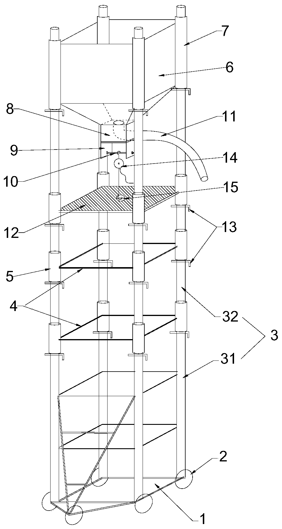
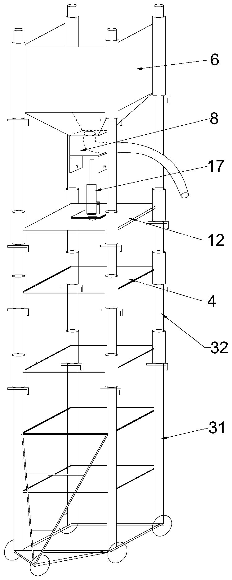
[0039] combine Figure 1-7 As shown, a height-adjustable concrete pouring frame includes a cubic frame arranged in the vertical direction. The cubic frame includes a base 1, and rollers 2 are arranged on the lower part of the base 1; Rods 3, adjacent support rods 3 are connected to each other through horizontal movable support frames 4 to reinforce the frame

[0040] The support rod 3 includes a main support rod 31 and an extension rod 32 ; the lower end of the extension rod 32 is ...


PUM


Abstract

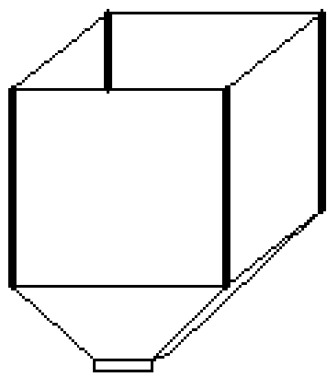
The invention provides a height-adjustable concrete pouring frame. The height-adjustable concrete pouring frame comprises a cubic frame composed of vertical supporting rods formed by assembling main supporting rods and extension rods, wherein a bearing supporting frame is arranged on the frame; a pouring funnel is arranged at the top of the frame; drill holes are formed in the supporting rods, andpositioning pins for limiting the bearing supporting frame and the pouring funnel are arranged in the holes; chain blocks for lifting the bearing supporting frame are arranged below the pouring funnel; and jacks for jacking the pouring funnel are arranged on the bearing supporting frame. The invention further provides a manufacturing method of the height-adjustable concrete pouring frame. The manufacturing method comprises the steps that after the main supporting rods are installed, the main supporting rods are sleeved with the horizontal movable supporting rods and the bearing supporting frame, and the extension rods are taken to be connected to the top ends of the main supporting rods, so that the height of the frame is increased; the pouring funnel is installed at the top of the frameand positioned through the positioning pins; the chain blocks are installed on a bearing box, and the bearing supporting frame is lifted; the frame is heightened again, the chain blocks are taken down, the jacks are placed on the bearing supporting frame, and the pouring funnel is jacked; and the chain blocks are installed again to lift the bearing supporting frame, and the chain blocks and the jacks are repeatedly exchanged and used till the pouring funnel is lifted to the height meeting the construction requirement.

Description

technical field [0001] The invention relates to a building construction device, in particular to a height-adjustable concrete pouring frame and a manufacturing method thereof. Background technique [0002] With the continuous development of the economy, the continuous progress of the society, the process of urbanization is getting faster and faster, and the scale of the city is getting bigger and bigger. The original drainage pipes can no longer meet the growing drainage requirements. Because there are a large number of criss-crossing pipelines under the original municipal road, if the original drainage pipes are replaced with large-diameter pipes, the original pipelines will also need to be readjusted, which brings great difficulty to the construction. In the case that the integrated pipe gallery has not been fully popularized, the modular drainage trench has become more and more choices. During the concrete pouring process of the modular trench, due to the shortage of cons...

Claims


Application Information

Patent Timeline
Patent Type & Authority Applications(China)
IPC IPC(8): E03F3/06
CPCE03F3/06
Inventor 石巍峰刘玉龙郑有为杨东雪晓强
Owner CHINA 22MCC GROUP CORP
Learn More