Rotary-type water decanter

A decanter and rotary technology, which is applied in the field of rotary decanters, can solve the problems that the decanting flow and skimming effect are affected by wind and waves, the structure of the driving device and the transmission device is complicated, and the decanting is uneven. Compact, rigid, and evenly decanted

Active Publication Date: 2012-07-04
广东新环环保产业集团有限公司
View PDF3 Cites 0 Cited by
  • Summary
  • Abstract
  • Description
  • Claims
  • Application Information

AI Technical Summary

Problems solved by technology

[0017] The purpose of the present invention is to provide a rotary decanter, which solves the problems of the existing decanters, such as the decanting flow and skimming effect are greatly affected by wind and waves, the decanting is uneven, and the structure of the driving device and the transmission device is complicated.

Method used


Image

  • Rotary-type water decanter
  • Rotary-type water decanter
  • Rotary-type water decanter

Examples


Embodiment 1

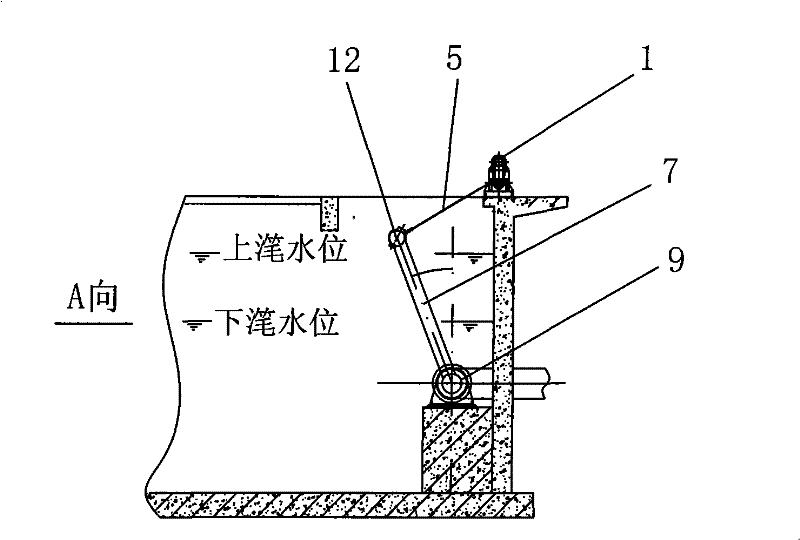
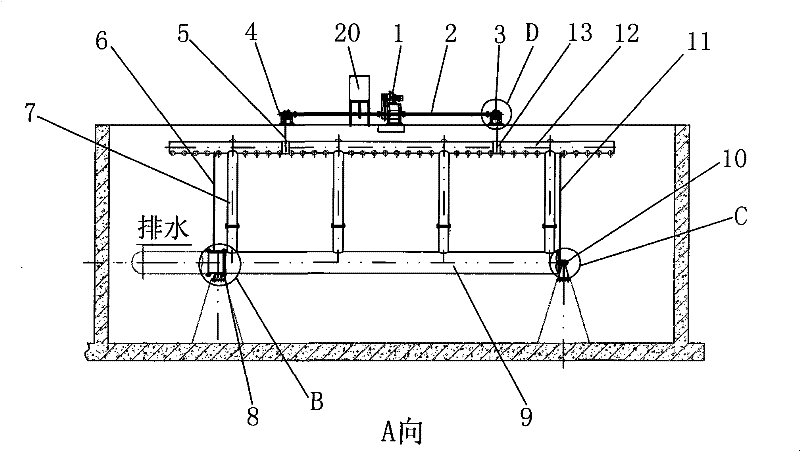
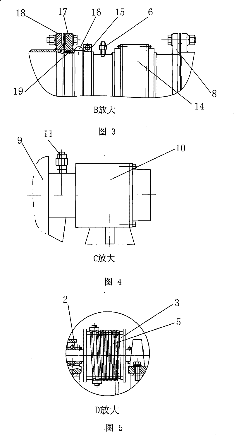
[0030] Example 1, such as figure 1 , 2 , 3, 4, and 5, a rotary decanter, including a driving device connected to a transmission device, a decanting tube group with one end connected to the transmission device and the other end hinged on the support of the pool, and a control system for controlling the operation of the driving device; The control system includes a stroke sensor 4 and a field control box 20 . The transmission device includes a reel 3 and a flexible rope 5 thereon. The set of decanting water pipes includes decanting water pipes 12 , at least one drainage branch pipe 7 and water outlet pipe 9 which communicate with each other. A row of water inlet holes is arranged at the bottom of the decanting pipe 12 .

[0031] The joint point of the lower end of flexible traction rope belt 5 and decanter is above the water surface all the time.

[0032] In order to lubricate and seal the underwater components, a first water diversion pipe 6 and a second water diversion pip...

Embodiment 2

[0034] Embodiment 2, in order to be suitable for decanting water in large pools, a transmission shaft 2 parallel to the decanting tube group is set between the driving device coupling transmission device; the two ends of the transmission shaft 2 are respectively provided with a reel 3 and its The transmission device of the flexible rope belt 5 on. All the other are with embodiment 1.

[0035] The working principle of the present invention: the motor direct-connected reducer in the driving device transmits the rotary motion to the two reel groups synchronously, and pulls the decanter pipe, water diversion pipe, central drain pipe, and PO combined seal around the pipe center line of the water pipe group 9 to work Rotational movement. The closed-loop control system composed of the on-site control box 20 and the stroke sensor 4 adjusts the rotation speed and direction in good time according to the set program to realize the following actions: the driving device 1 drives the reel ...


PUM


Abstract

The invention relates to a rotary-type water decanter, comprising a driving device, a transmission device, a water decanting pipe set and a control system, wherein the driving device is linked with the transmission device; one end of the water decanting pipe set is linked with the transmission device and the other end thereof is hinged on the support of a water pool; and the control system controls the driving device to work. The control system comprises a stroke sensor and a spot control box. The transmission device comprises a wound roll and a flexible rope belt, wherein the rope belt is arranged on the wound roll. The water decanting pipe set comprises water decanting pipes, at least one branch drainpipe and at least one water outlet pipe, wherein the water decanting pipes, the branch drainpipe and the water outlet pipe are communicated with one another. A row of water inlet openings are arranged at the bottoms of the water decanting pipes. By adopting a flexible hoist driving device, field occupation space is smaller and transmission efficiency is high. By adopting the structure of a vent hole and a lower opening ring hole, the manufacturability, the stability and the rigidityare good, water decanting is even, the water-entering floating power of the undercurrent and water collection structure is much less than the gravity, and water decanting flow rate and scumming effectare less influenced by wind and wave. The rotary-type water decanter has the high operating efficiency of the whole device, can save 60 percent electrical energy, and has long service life.

Description

technical field [0001] The invention relates to a decanter, in particular to a rotary decanter. It is mainly used in various intermittent sewage treatment systems such as SBR process (sequenced batch activated sludge reactor treatment process). It is a new type of rotary rigid tube decanting device without underwater transmission parts and screw transmission. Background technique [0002] The working method of the rotary decanter is that in the drainage stage, the decanter pipe rotates downward to automatically decant the water, and the supernatant of the reaction tank is evenly discharged, while the scum on the surface of the pool is effectively trapped in the reaction tank, and decanted at the end of the drainage. The quick return of the water pipe stops at a position higher than the water surface of the pool to ensure the quality of the effluent water. At present, the known rigid tube rotary decanter includes a rotary decanter structure composed of a skimming device, an...

Claims


Application Information

Patent Timeline
Patent Type & Authority Patents(China)
IPC IPC(8): B01D21/24C02F3/12
CPCY02W10/10
Inventor 黄桂华程鉴昌张新陈志敏刘凯俊
Owner 广东新环环保产业集团有限公司
Why Eureka
Try Eureka