Electrical Equipment Condition Monitoring and Fault Warning System

A technology for early warning of electrical equipment and failures, applied in the direction of electrical transmission signal systems, alarms, measuring devices, etc., can solve problems such as secondary failures, large losses in sudden accidents, and a large number of network management, and achieve the goal of improving the normal operation rate Effect

Active Publication Date: 2021-11-02
深圳红电智能技术有限公司
View PDF5 Cites 0 Cited by
  • Summary
  • Abstract
  • Description
  • Claims
  • Application Information

AI Technical Summary

Problems solved by technology

[0002] Most of the existing traditional diagnostic instruments at home and abroad are environmental temperature monitoring, single video monitoring and infrared single point monitoring. There are many detection nodes, because there will be secondary faults caused by the binding of online growth, there is no calculation and storage of image data, the calculation at the end of the cabinet cannot be done, and the monitoring and imaging of the power distribution cabinet door cannot be closed on site; (2) Online dual-wave Detection, one host and one infrared detection, but the area is small, the cost is high, and the number of network management is large; (3) hand-held mobile infrared thermal imaging detection requires patrol-type collection of data, and cannot return fault prediction information in real time, and cannot Immediate emergency treatment in case of failure, once a sudden accident occurs, the loss will be huge

Method used


Image

  • Electrical Equipment Condition Monitoring and Fault Warning System

Examples


Embodiment Construction

[0026] In order to make those skilled in the art more clearly understand the purpose, technical solutions and advantages of the present invention, the present invention will be further described below in conjunction with the accompanying drawings and embodiments.

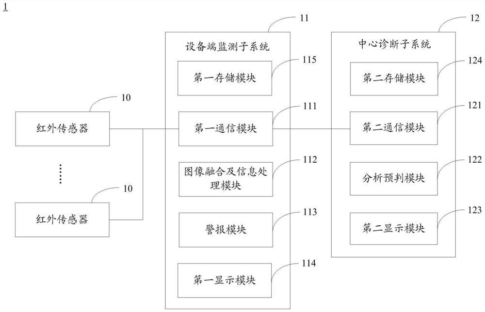
[0027] refer to figure 1 , figure 1 It is a system block diagram of an embodiment of the electrical equipment status monitoring and fault early warning system 1 of the present invention. In the embodiment shown in the drawings, the electrical equipment status monitoring and fault warning system 1 includes: a plurality of infrared sensors 10 arranged in different parts of the electrical equipment, an equipment end monitoring subsystem 11 and an equipment end monitoring The subsystem 11 is communicatively connected to the central diagnostic subsystem 12 .

[0028] Wherein, the infrared sensor 10 is used to collect infrared thermal imaging data of different parts in the electrical equipment. In this embodiment, the i...


PUM


Abstract

The invention discloses a state monitoring and fault early warning system for electrical equipment, comprising: a plurality of infrared sensors arranged in different parts of the electrical equipment and an equipment end monitoring subsystem, wherein the infrared sensors are used to collect different Infrared thermal imaging data of parts; the equipment-side monitoring subsystem is used to fuse infrared thermal imaging data from multiple infrared sensors with visible light images of electrical equipment to obtain a fused image, and judge each part of the electrical equipment according to the fused image Whether the detected temperature exceeds its preset threshold, and if it exceeds the preset threshold, an early warning will be given and a fusion image will be displayed. Compared with the prior art, the present invention intuitively displays the temperature of the internal parts of the electrical equipment in an image manner through image fusion and recognition and infrared temperature field diagnosis technology, and can understand the working temperature of the internal components of the electrical equipment in real time, so that the user can timely Find the internal fault location of electrical equipment for easy maintenance.

Description

technical field [0001] The invention relates to the field of operation and maintenance of electrical equipment, and more particularly relates to a state monitoring and fault early warning system for electrical equipment. Background technique [0002] Most of the existing traditional diagnostic instruments at home and abroad are environmental temperature monitoring, single video monitoring and infrared single point monitoring. There are many detection nodes, because there will be secondary faults caused by the binding of online growth, there is no calculation and storage of image data, the calculation in the cabinet cannot be done, and the monitoring and imaging cannot be performed by closing the power distribution cabinet door on site; (2) Online dual-wave Detection, one host and one infrared detection, but the area is small, the cost is high, and the number of network management is large; (3) hand-held mobile infrared thermal imaging detection requires patrol-type collectio...

Claims


Application Information

Patent Timeline
Patent Type & Authority Patents(China)
IPC IPC(8): G01J5/00G06K9/62G08B7/06G08B21/18
CPCG01J5/00G01J5/0003G08B21/182G08B7/06G01J2005/0077G06F18/251
Inventor 王滨
Owner 深圳红电智能技术有限公司
Why Eureka
Try Eureka