Current acquisition circuit

An acquisition circuit and current sampling technology, applied in the field of current acquisition circuit, can solve the problems of automatic influence, sampling accuracy disclosure, single voltage and current sampling circuit, etc., and achieve good robustness

Inactive Publication Date: 2020-05-26
XIAN ZHISHENG RUIXIN SEMICON TECH CO LTD
View PDF0 Cites 0 Cited by
  • Summary
  • Abstract
  • Description
  • Claims
  • Application Information

AI Technical Summary

Problems solved by technology

In order to detect the large current in these devices, it needs to be sampled and then detected. The voltage and current sampling circuit of the existing device is too simple, and the sampling accuracy is revealed, resulting in subsequent processing of phase voltage, line voltage, phase current, line current, The results of power factor, zero-sequence voltage, zero-sequence current, frequency, and harmonics have large deviations, which have a great impact on the automation of device operation

Method used


Image

  • Current acquisition circuit

Examples


Embodiment 1

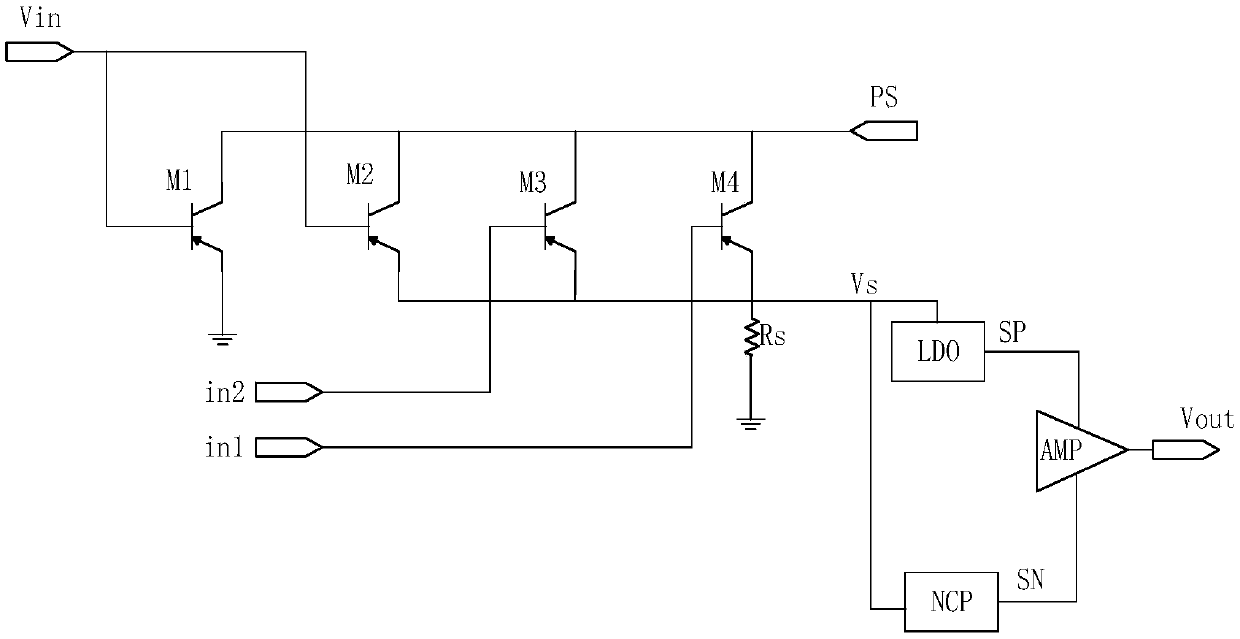
[0015] like figure 1 As shown, the current sampling circuit includes a pin Ps, a shunt transistor M1, sampling transistors M2, M3, M4, and a sampling resistor Rs, wherein the shunt transistor M1, sampling transistors M2, M3, and M4 are power NMOS transistors, and the shunt transistor M1 and sampling The gate of the transistor M2 is connected to the power supply Vin, therefore, the shunt transistor M1 and the sampling transistor M2 are in a normally-on state, which is a fixed access state. The gate of the sampling transistor M3 is connected to the external input pin in1, the gate of the sampling transistor M4 is connected to the external input pin in2, and the external input pin controls the sampling transistor M3 and the sampling signal through the sampling signal provided to the sampling transistor M3 and the sampling transistor M4. Transistor M4 is turned on and off. When the gate signals of the sampling transistor M3 and the sampling transistor M4 are at a high level, the ...


PUM


Abstract

The invention relates to a current acquisition circuit. The circuit comprises a current sampling circuit and an amplifying circuit, the current sampling circuit comprises drain electrode connecting pins Ps of a shunt transistor M1 and sampling transistors M1, M2 and M4. Grid electrodes of the shunt transistor M1 and the sampling transistor M2 are connected with a power supply Vin, the grid electrodes of the sampling transistors M3 and M4 are respectively connected with a signal input pin, the source electrodes of the sampling transistors M2, M3 and M4 are connected with the first end of a sampling resistor Rs, and the second end of the resistor Rs is grounded; the amplifying circuit comprises a low dropout regulator; wherein the low dropout linear regulator and the negative charge pump arerespectively connected with the source electrodes of the sampling transistors M2, M3 and M4 and the connection node of the sampling resistor Rs, and the output end of the low dropout linear regulatorand the output end of the negative charge pump are connected to the amplifier. According to the embodiment of the invention, two current values can be detected by arranging the two signal input pins,so that sampling detection of various current values is realized.

Description

technical field [0001] The invention belongs to the technical field of voltage and current sampling, and in particular relates to a current sampling circuit. Background technique [0002] With the development of our country's economy, the modernization of enterprise operation and the improvement of automation are related to the development of the national economy. The reliability and stability requirements of power operation cannot be ignored; Equipped with protection, metering, automation and other devices. In order to detect the large current in these devices, it needs to be sampled and then detected. The voltage and current sampling circuit of the existing device is too simple, and the sampling accuracy is revealed, resulting in subsequent processing of phase voltage, line voltage, phase current, line current, Power factor, zero-sequence voltage, zero-sequence current, frequency, harmonics and other results have large deviations, which have a great impact on the automati...

Claims


Application Information

Patent Timeline
Patent Type & Authority Applications(China)
IPC IPC(8): G01R19/25
CPCG01R19/25
Inventor 李艳娥张亮刘玲玲
Owner XIAN ZHISHENG RUIXIN SEMICON TECH CO LTD
Why Eureka
Try Eureka