
Response combined antenna compatible with omnidirectional communication and satellite navigation

A technology of satellite navigation and combined antenna, which is applied in the direction of independent antenna unit combination, antenna, antenna coupling, etc., can solve the problems of single-cone antenna lowering antenna installation requirements, single-cone antenna cannot meet the platform, and structure is not strong enough, etc., to achieve structural Compact, simple and reliable connection, strong anti-interference ability

Active Publication Date: 2020-05-26
10TH RES INST OF CETC
View PDF19 Cites 2 Cited by
  • Summary
  • Abstract
  • Description
  • Claims
  • Application Information

AI Technical Summary

Problems solved by technology

Although this combined design solved the problem of combining the single-cone antenna and GPS antenna at that time, with the continuous development of satellite guidance technology and the continuous improvement of the platform's antenna requirements, the single-cone antenna cannot meet the existing needs of the platform.
The disadvantage of the single-cone antenna is that the single-cone navigation antenna only supports the GPS function. Due to reasons such as structure and electrical performance, the contact area between the bottom of the single-cone antenna cone and the floor is too small, and the structure is not strong enough.
Since the height of the existing single-cone antenna cannot meet the requirements of improving the overall performance of the existing platform and further reduce the installation requirements of the antenna section height, it is necessary to further reduce the height dimension

Method used


Image

  • Response combined antenna compatible with omnidirectional communication and satellite navigation
  • Response combined antenna compatible with omnidirectional communication and satellite navigation
  • Response combined antenna compatible with omnidirectional communication and satellite navigation

Examples


Embodiment Construction

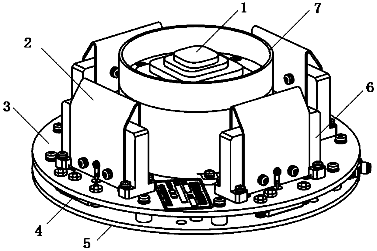
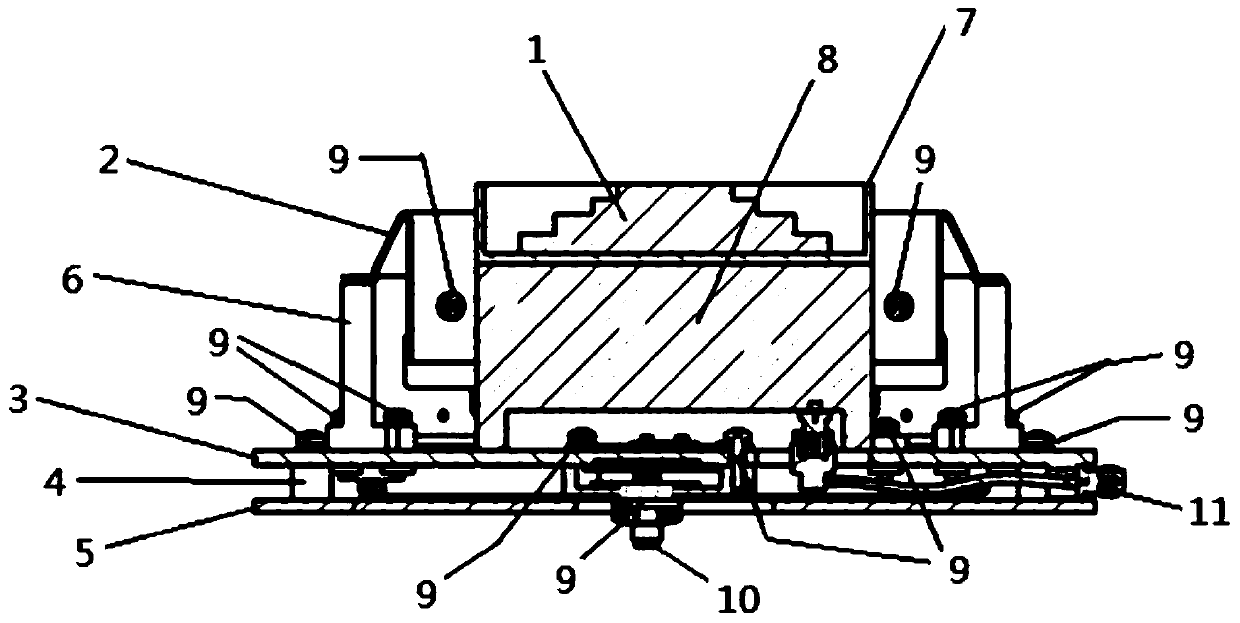
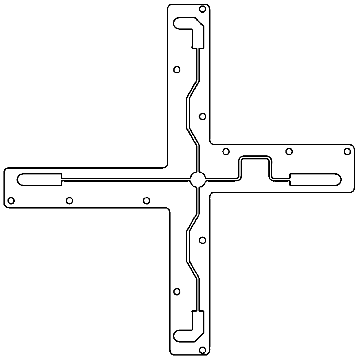
[0020] refer to Figure 1-Figure 5 . In the preferred embodiment described below, a combined response antenna compatible with omnidirectional communication and satellite navigation includes: a seat plate 5 fixedly connected by a circumferential column, and a shielding cylinder fixed vertically at the center of the seat plate 5 7 and the navigation system antenna 1 assembled on the shielding cylinder, the response antenna distributed around the shielding cylinder circular array, wherein: the navigation system antenna 1 is fixed on the combination of the shielding cylinder 7 without the upper cover plate and the seat plate 5 In the cylindrical cavity, the navigation system antenna includes a multi-layer microstrip antenna 1 and an amplifying circuit module 8 connected in sequence, and the response antenna 2 is fixed vertically on the surface of the base plate 5 and distributes the vertical plate 6 around the circular array of the shielding cylinder. It is composed of the foldin...


PUM


Abstract

The invention discloses a response combined antenna compatible with omnidirectional communication and satellite navigation, and aims to provide a combined antenna which is smaller in height, strong inanti-interference capability, high in transportability and compatible with navigation and communication response functions. The combined antenna is realized through the following technical scheme: anavigation system antenna is fixed in a cylindrical cavity and comprises a multilayer microstrip antenna and an amplifying circuit module which are connected in sequence, a response antenna is composed of vertical plates which are vertically and fixedly connected to the surface of a base plate and distributed around a shielding cylinder in a circular array mode, folding oscillators respectively fixed on the vertical plates and a power divider assembled with a bottom plate interlayer of a lower base plate, and the power divider feeds the folding oscillators through the bottom plate interlayer;the amplifying circuit module amplifies and filters each path of radio frequency signals from the multilayer microstrip antenna, and the radio frequency signals of the satellite navigation antenna areoutput after the radio frequency signals are combined by a multiplexer in the amplifying circuit module. According to the invention, the satellite antenna or the response antenna can be replaced according to different application platform requirements so as to meet multi-platform application.

Description

technical field [0001] The invention relates to a combined antenna compatible with three-system satellite navigation and omnidirectional communication response functions. Background technique [0002] With the rapid development of communication technology, antennas are facing the challenges of miniaturization, multi-band, and integration. With the increasing number of electronic devices, multiple antennas are usually combined and installed together to work together, making the antennas on the platform staggered and numerous, resulting in a complex electromagnetic environment on the device, and even affecting the normal communication of the device. Therefore, how to effectively solve the above problems and design a multifunctional combined antenna with excellent performance is challenging. [0003] In many systems, the transmission and reception of electromagnetic waves must be realized through antennas. Antenna is the transceiver device of communication equipment, and the ...

Claims


Application Information

Patent Timeline
Patent Type & Authority Applications(China)
IPC IPC(8): H01Q1/12H01Q1/36H01Q1/38H01Q1/50H01Q1/52H01Q9/30H01Q21/00H01Q21/30H01Q23/00
CPCH01Q1/12H01Q1/36H01Q1/38H01Q1/50H01Q1/526H01Q9/30H01Q21/0006H01Q21/30H01Q23/00
Inventor 侯禄平阳昆苟能亮谢义水兰鹍温剑张云
Owner 10TH RES INST OF CETC
Learn More