
Large-specification large-height-diameter-ratio magnesium alloy casting rod continuous upsetting blank making method

A magnesium alloy, high-diameter ratio technology, applied in the direction of manufacturing tools, metal processing equipment, forging/pressing/hammering machinery, etc., can solve problems such as inability to deform, instability of cylindrical blanks, double drums, etc., and achieve mechanical Improve performance, reduce production cost, and overcome the effect of long process flow

Active Publication Date: 2020-05-29
ZHONGBEI UNIV
View PDF5 Cites 5 Cited by
  • Summary
  • Abstract
  • Description
  • Claims
  • Application Information

AI Technical Summary

Problems solved by technology

In particular, when the aspect ratio is greater than 3, the cylindrical blank will experience instability, resulting in "double drums" and folding defects, making subsequent deformation impossible.

Method used


Image

  • Large-specification large-height-diameter-ratio magnesium alloy casting rod continuous upsetting blank making method
  • Large-specification large-height-diameter-ratio magnesium alloy casting rod continuous upsetting blank making method
  • Large-specification large-height-diameter-ratio magnesium alloy casting rod continuous upsetting blank making method

Examples


Embodiment Construction

[0032] The present invention will be described in detail below in conjunction with the accompanying drawings and specific embodiments.

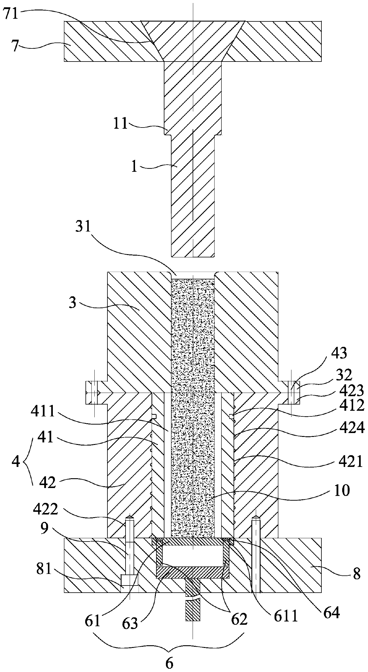
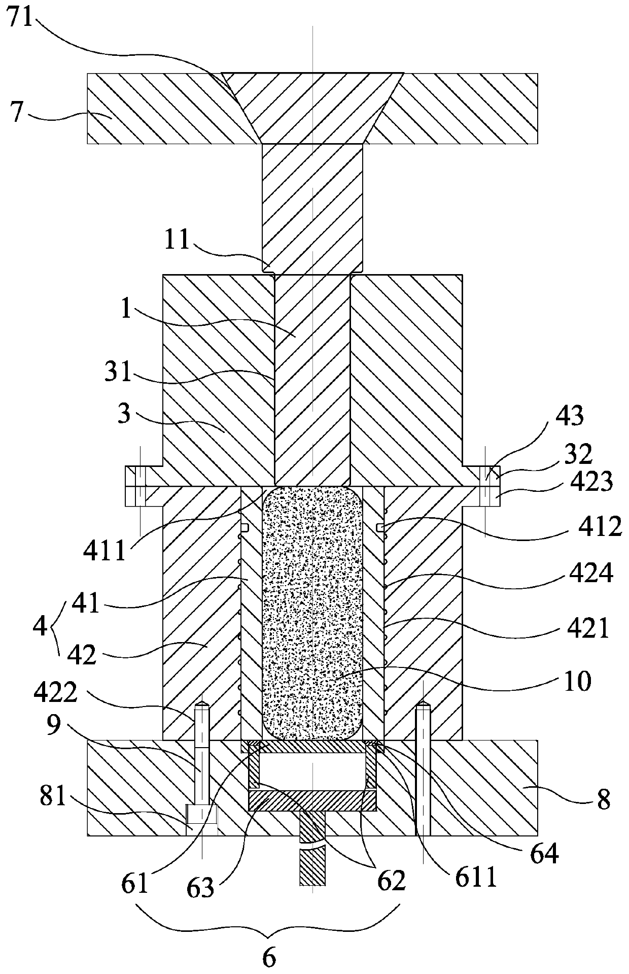
[0033] The present invention relates to a magnesium alloy cast rod continuous upsetting billet mold, comprising a punch 1 installed on the upper workbench (not shown in the figure) of the press, a punch collar 2, an upper die 3, a lower die Die 4, snap ring 5, ejector rod mechanism 6, fastener (not shown in the figure), punch fixed plate 7, die fixed plate 8 and bolt 9, as figure 2 As shown; the punch fixing plate 7 is fixed on the upper workbench, and the middle part of the punch fixing plate 7 is provided with a funnel-shaped through hole 71, and the top of the punch 1 is funnel-shaped, and the punch 1 is inserted from the through hole 71 and connected with the through hole 71. The holes 71 are closely matched, and the funnel-shaped design simplifies and stabilizes the installation of the punch 1 .

[0034] The upper die 3 is coaxially in...


PUM


Abstract

The invention discloses a large-specification large-height-diameter-ratio magnesium alloy casting rod continuous upsetting blank making method. The large-specification large-height-diameter-ratio magnesium alloy casting rod continuous upsetting blank making method comprises the following steps that (1) blanking is conducted; (2) homogenization treatment is conducted; (3) a blank and a die are heated and heat preservation is conducted; (4) the blank is placed in a second lower cavity; (5) a male die downwards moves to extrude the blank to completely enter the second lower cavity; (6) an upper female die is firstly removed and a T-shaped ejector rod upwards moves, a vertical rod is pushed to extend upwards from a vertical groove and ejected out of an inner female die until a ring groove of the inner female die exposed out an external female die, and a clamping ring is clamped into the ring groove; (7) the ejector rod descends and resets to drive the vertical rod to contract and reset, the male die moves upwards and leaves the blank, and the lower part of the male die is sleeved with a male die lantern ring; and (8) the male die moves downwards and enters the second lower cavity to extrude the bottom of the blank to gradually fill the first lower cavity, and the blank of the first lower cavity is started being ejected upwards out of the inner female die, meanwhile, the first lowercavity is continuously filled with the bottom blank, and after the top height of the blank is flush, the male die stops moving downwards. According to the large-specification large-height-diameter-ratio magnesium alloy casting rod continuous upsetting blank making method, an ejector rod mechanism is ingeniously used for movably changing the cavity structure, forming is fuller, stability is higher, and materials are saved.

Description

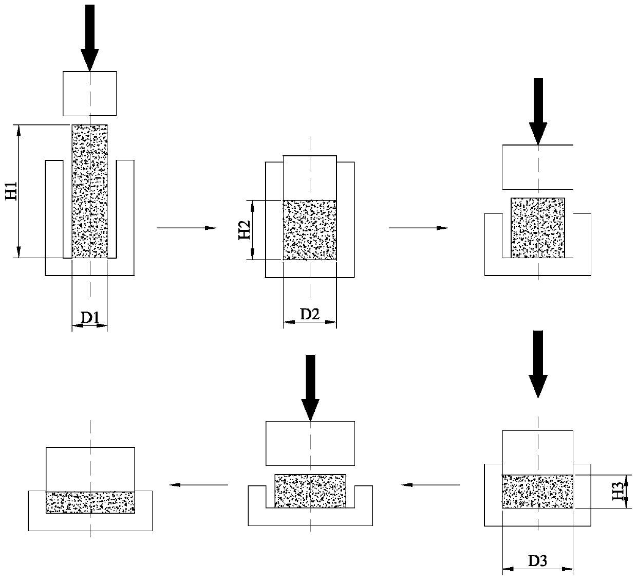
technical field [0001] The invention belongs to the metal extrusion forming technology, and is suitable for continuous large-deformation billet making of magnesium alloy cast rods with a large aspect ratio far greater than 3. Background technique [0002] Continuous upsetting deformation means that during the upsetting deformation process of cast rods (hereinafter referred to as bars or billets), different working sections are continuously changed by changing different punches, dies, etc. strain, so as to achieve the purpose of grain refinement, the principle diagram is as follows figure 1 shown. The first step: place the D1×H1 blank in the first set of molds for the first upsetting forming, and the size of the blank after completion is D2×H2; the second step: place the D2×H2 blank in the second set of molds The second upsetting process is carried out, and the size of the blank after completion is D3×H3 (upsetting can be continued to obtain the desired blank size), so far,...

Claims


Application Information

Patent Timeline
Patent Type & Authority Applications(China)
IPC IPC(8): B21J5/00B21J5/08B21J13/02B21J13/14
CPCB21J5/002B21J5/08B21J13/02B21J13/14
Inventor 孟模董蓓蓓张治民于建民车鑫王强高植史铮
Owner ZHONGBEI UNIV
Learn More