
Metal cutting machine tool for cleaning iron chips during cutting

A metal cutting and cutting machine technology, which is applied to metal processing machinery parts, metal processing equipment, maintenance and safety accessories, etc., can solve the problems of affecting processing accuracy, increased tool vibration, and tool rotation friction, etc., to improve processing accuracy, Reduced friction rate and vibration reduction effect

Active Publication Date: 2020-05-29
安徽佰易智能精机制造有限公司
View PDF10 Cites 1 Cited by
  • Summary
  • Abstract
  • Description
  • Claims
  • Application Information

AI Technical Summary

Problems solved by technology

[0004] The main purpose of the present invention is to overcome the deficiencies of the prior art, and to provide a metal cutting machine tool for cleaning iron filings during cutting, so as to solve the cutting process. The cutting tools process the arranged workpieces one by one, and the iron filings will fly and fall on the periphery of the workpieces. The more iron filings accumulate around the post-processed workpiece, the tool is prone to friction when rotating, causing the tool to vibrate and affecting the machining accuracy. As the iron filings thicken, the cutting tool is rubbed and braked by the iron filings during rotation, and the tool is stuck. The problem that the jitter also increases after the pause

Method used


Image

  • Metal cutting machine tool for cleaning iron chips during cutting
  • Metal cutting machine tool for cleaning iron chips during cutting
  • Metal cutting machine tool for cleaning iron chips during cutting

Examples


Embodiment 1

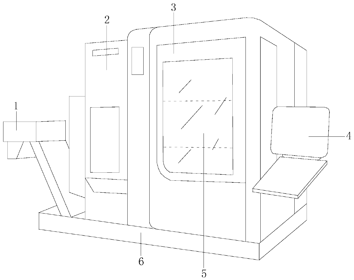
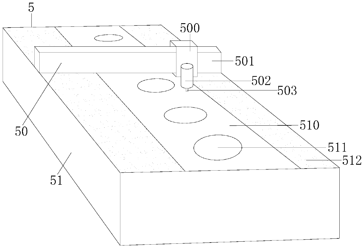
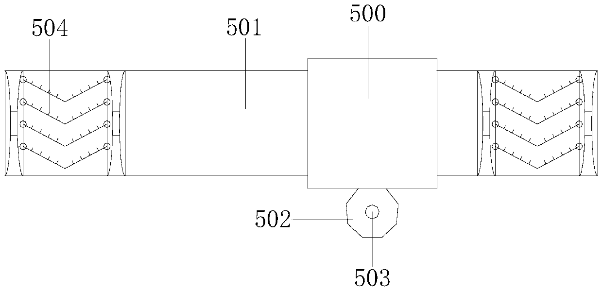
[0027] Example 1 see Figure 1-6 , the present invention provides a technical solution for metal cutting machine tools for cleaning iron chips during cutting: its structure includes a feeding rack 1, a cutting fluid storage rack 2, a cutting chamber 3, a control machine 4, a cutting machine 5, and a base 6. The cutting fluid The storage rack 2 is used to cool and lubricate the cutting tool and the workpiece. The feeding rack 1 and the cutting fluid storage rack 2 are installed on the base 6, the cutting chamber 3 is locked with the base 6, and the control machine 4 is locked in the cutting chamber 3 Above, the cutting machine 5 is installed on the cutting chamber 3, the cutting machine 5 is composed of a cutting head 50 and a workpiece frame 51, the cutting head 50 is connected with the workpiece frame 51 track, and the cutting head 50 includes Mobile machine frame 500, cross rail 501, cutting machine barrel 502, cutting machine drill 503, and dust attachment device 504. The m...

Embodiment 2

[0029] Example 2 see Figure 7 , the present invention provides a technical solution for metal cutting machine tools for cleaning iron filings during cutting: the structure of the dust attachment device 504 includes a bezel 90, a turning shaft 91, and a dust attachment structure 92, and the bezel 90 and the turning shaft 91 are locked , the turning shaft 91 is axially connected with the dust attachment structure 92, and the rotation of the turning shaft 91 drives the lifting of the dust attachment structure 92, which can pinch and clean relatively thick iron filings in a targeted manner. The dust attachment structure 92 It includes a turning shaft circle 920 , attached scales 921 , and mounting strips 922 , the fitting strips 922 are axially connected to the frame 90 through the turning shaft circles 920 , and the attached scales 921 are installed on the fitting strips 922 .

[0030] The bezel 90 cleans the iron filings at the dust attachment plate 512, the horizontal rail 501 m...


PUM


Abstract

The invention discloses a metal cutting machine tool for cleaning iron chips during cutting. The metal cutting machine tool structurally includes a feeding frame, a cutting fluid storage frame, a cutting chamber, a control machine, a cutting machine and a base. The feeding frame and the cutting fluid storage frame are installed on the base, the cutting chamber and the base are locked, the controlmachine is locked on the cutting chamber, the cutting machine is installed on the cutting chamber, the cutting machine is composed of a cutting machine head and a workpiece frame, and the cutting machine head is in track connection with the workpiece frame. The cutting machine head includes a moving machine frame, a cross track, a cutting machine barrel, a cutting machine drill, and a dust collecting device. The moving machine frame is in track connection with the cross track, the dust collecting device is embedded in the cross track, the moving machine frame is welded to the cutting machine barrel, and the cutting machine barrel is connected with a cutting machine drill spindle. According to the metal cutting machine tool, the cutting machine drill collects and cleans the iron chips whileturning, the friction rate with the iron chips is reduced when the cutting structure is machined, the vibration is reduced, and the machining accuracy is further improved; and the iron chips accumulated around are further evenly cleaned by an embedded frame, so that the friction brake due to the thickening of the iron chips is avoided, and the equipment operates more smoothly.

Description

technical field [0001] The invention relates to the technical field of mechanical processing equipment, in particular to a metal cutting machine tool for cleaning iron filings during cutting. Background technique [0002] The metal cutting process is the relative movement between the workpiece and the tool. The tool removes excess metal from the workpiece to be processed, so that the workpiece can obtain geometric accuracy, dimensional accuracy and surface quality that meet the design and process requirements. [0003] In the cutting process of the prior art, the cutting tool processes the arranged workpieces one by one, and the iron chips will fly and fall around the workpieces. The more iron filings are accumulated around the workpieces that are processed later, the tool is prone to friction when it rotates, causing the tool to vibrate. It affects the machining accuracy. As the iron filings thicken, the cutting tool is braked by the friction of the iron filings during rota...

Claims


Application Information

Patent Timeline
Patent Type & Authority Applications(China)
IPC IPC(8): B23Q11/00
CPCB23Q11/0042
Inventor 王康康
Owner 安徽佰易智能精机制造有限公司
Learn More