Rapid feeding machine for hydraulic machine

Inactive Publication Date: 2020-05-29
太田机械江苏有限公司
View PDF8 Cites 2 Cited by
  • Summary
  • Abstract
  • Description
  • Claims
  • Application Information

AI Technical Summary

Problems solved by technology

[0004] The purpose of the present invention is to provide a quick feeder for hydraulic presses, to solve the problem that the existing quick feeder for hydraulic presses proposed in the above background technology generally has a relatively simple structure, does not have a liftable structure, and cannot adjust the loading Therefore, it cannot be applied to hydraulic presses of different heights, and it does not have a buffer structure that can adjust the inclination angle during loading or unloading, resulting in accidental damage to the workpiece due to height differences during loading.

Method used

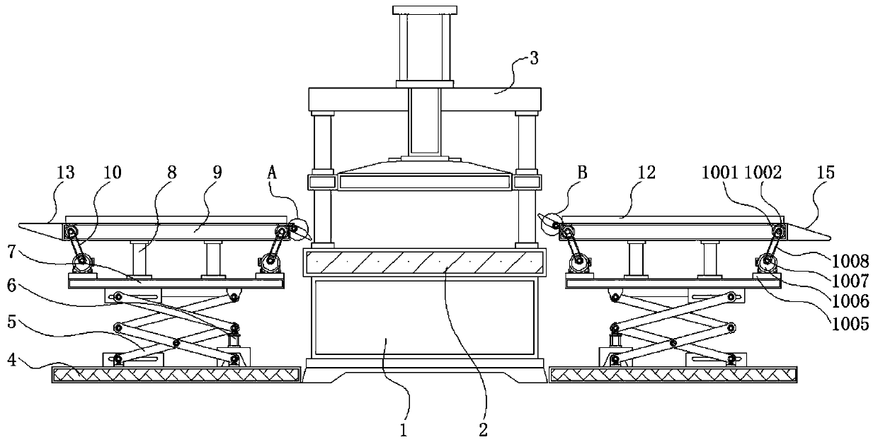
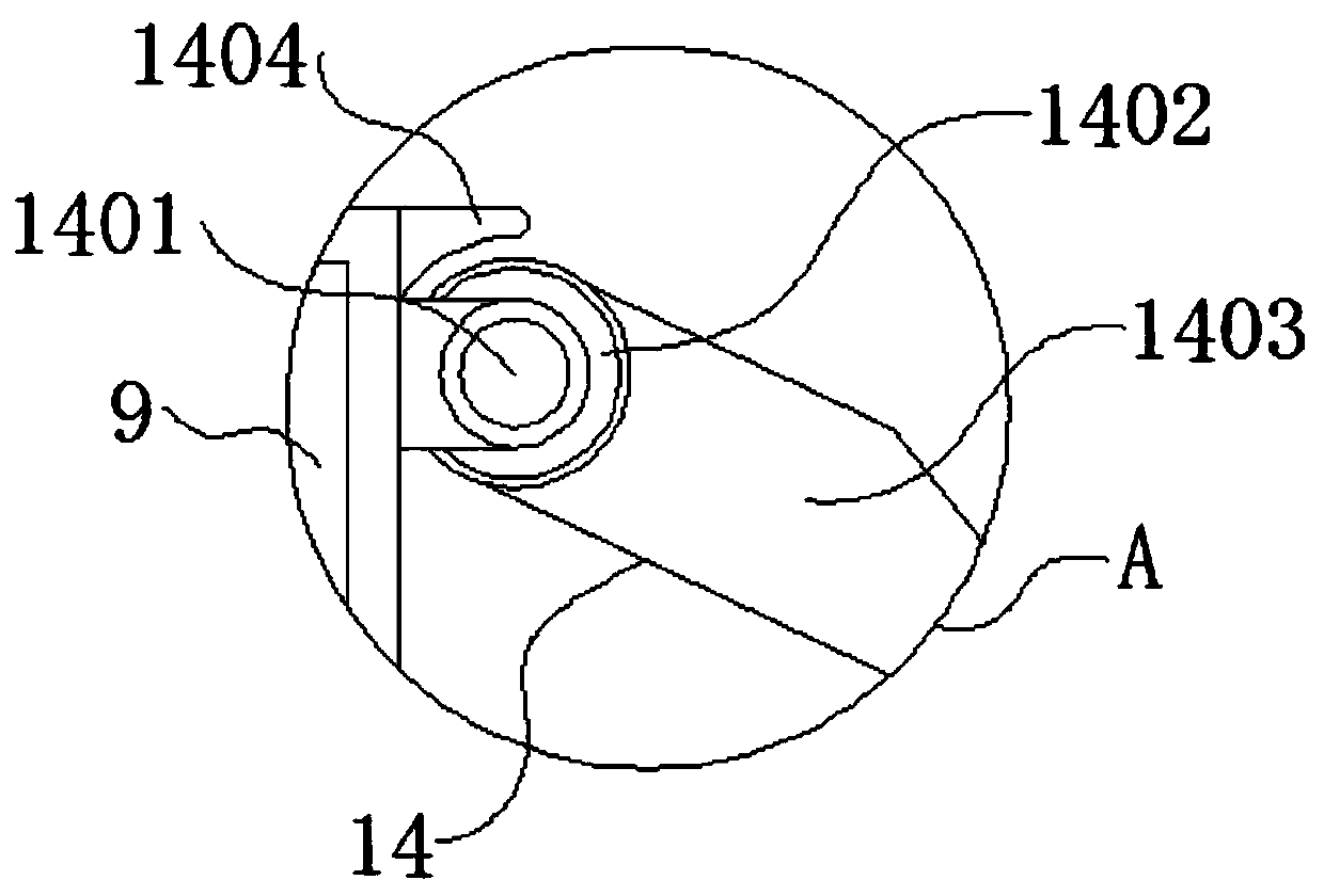
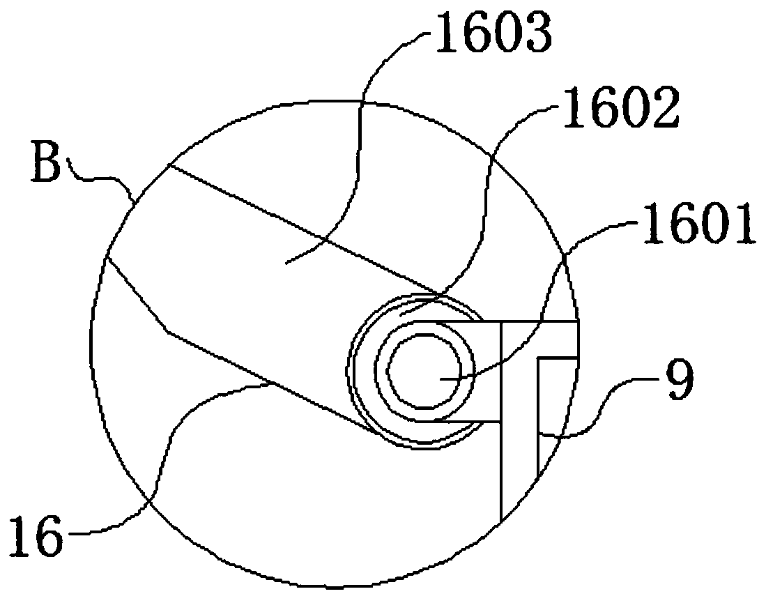

Image

  • Rapid feeding machine for hydraulic machine
  • Rapid feeding machine for hydraulic machine
  • Rapid feeding machine for hydraulic machine

Examples


Embodiment Construction

[0025] The following will clearly and completely describe the technical solutions in the embodiments of the present invention with reference to the accompanying drawings in the embodiments of the present invention. Obviously, the described embodiments are only some, not all, embodiments of the present invention. Based on the embodiments of the present invention, all other embodiments obtained by persons of ordinary skill in the art without making creative efforts belong to the protection scope of the present invention.

[0026] In the description of the present invention, unless otherwise stated, the meaning of "plurality" is two or more; the terms "upper", "lower", "left", "right", "inner", "outer" , "front end", "rear end", "head", "tail", etc. indicate the orientation or positional relationship based on the orientation or positional relationship shown in the drawings, and are only for the convenience of describing the present invention and simplifying the description, rather...


PUM


Abstract

The invention discloses a rapid feeding machine for a hydraulic machine and relates to the technical field of hydraulic machines. The rapid feeding machine comprises a hydraulic machine main body andconveying mechanisms. A hydraulic machine workbench is fixed above the hydraulic machine main body. A fixed outer frame is mounted on the outer side of the upper portion of the hydraulic machine workbench. Bases are correspondingly arranged on the left side and the right side of the hydraulic machine main body. Hydraulic lifting arms are mounted above the bases. Hydraulic oil cylinders are arranged below one sides of the hydraulic lifting arms. Lifting seats are mounted above the hydraulic lifting arms. Support frames are fixedly arranged above the middle portions of the lifting seats. Mounting frames are mounted above the support frames. The conveying mechanisms are arranged inside the mounting frames. Dustproof shielding plates are fixedly arranged above the two sides inside the mountingframes. Protection barrier plates are fixedly arranged above the dustproof shielding plates. The rapid feeding machine has the beneficial effects that by arranging the hydraulic lifting arms and thehydraulic oil cylinders, the lifting seats are driven to lift up and down conveniently, the use is quite flexible, and the bases can stably support the lifting seats.

Description

technical field [0001] The invention relates to the technical field of hydraulic presses, in particular to a quick feeder for hydraulic presses. Background technique [0002] A hydraulic press (also known as: hydraulic press) is a machine that utilizes hydrostatic pressure, uses liquid as the working medium, and uses Pascal's principle to transfer energy to process metal, plastic, rubber, wood, powder and other products. In addition to being used for forging and forming, the hydraulic press can also be used for straightening, pressing, packing, briquetting and pressing. During the use of the hydraulic press, it is necessary to load and unload the processed products, so a feeder is required. [0003] The existing fast loading machine for hydraulic presses generally has a relatively simple structure, does not have a liftable structure, and cannot adjust the height of the loading position, so it cannot be applied to hydraulic presses of different heights, and when loading or u...

Claims


Application Information

Patent Timeline
Patent Type & Authority Applications(China)
IPC IPC(8): B30B15/30B30B1/32
CPCB30B1/32B30B15/30
Inventor 王爱军
Owner 太田机械江苏有限公司
Why Eureka
Try Eureka