Optimal setting method for road traffic deceleration facilities

A technology for road traffic and facilities, applied in the directions of roads, roads, road signs, etc., can solve the problems of affecting the driving comfort and stability of vehicles, the high cost of speed limit measures, the general application of speed limit measures, and the lack of perfect traffic speed limit measures. The effect of repeated use, promotion and use, easy promotion and use, and low cost

Inactive Publication Date: 2020-05-29
FOSHAN UNIVERSITY
View PDF6 Cites 0 Cited by
  • Summary
  • Abstract
  • Description
  • Claims
  • Application Information

AI Technical Summary

Problems solved by technology

[0003] At present, for the highways and municipal roads that have been in operation, various types of speed limit signs and mandatory deceleration facilities are widely used, and the deceleration effects vary. Some speed limit effects are poor, and some affect the driving comfort and stability of vehicles There are problems such as high project cost
For municipal roads whose construction has not been completed, especially high-grade highways, when the subgrade is completed, the road surface is wide and flat, and there are many cross-construction vehicles but there are no perfect and clear traffic speed limit measures. Random driving of vehicles may easily lead to safety accidents
For the traffic control of unfinished roads, due to the temporary and volatile nature of traffic control, the service cycle is short, so the cost of the commonly used speed limit measures is high and has not been widely used.

Method used


Image

  • Optimal setting method for road traffic deceleration facilities
  • Optimal setting method for road traffic deceleration facilities
  • Optimal setting method for road traffic deceleration facilities

Examples


Embodiment 1

[0038] In this embodiment, a highway half-width subgrade with a width of 12.25 m is taken as an example to describe the following. The half-width roadbed of the expressway has completed the construction of the base layer of the pavement, and is preparing to construct the lower layer of the asphalt pavement.

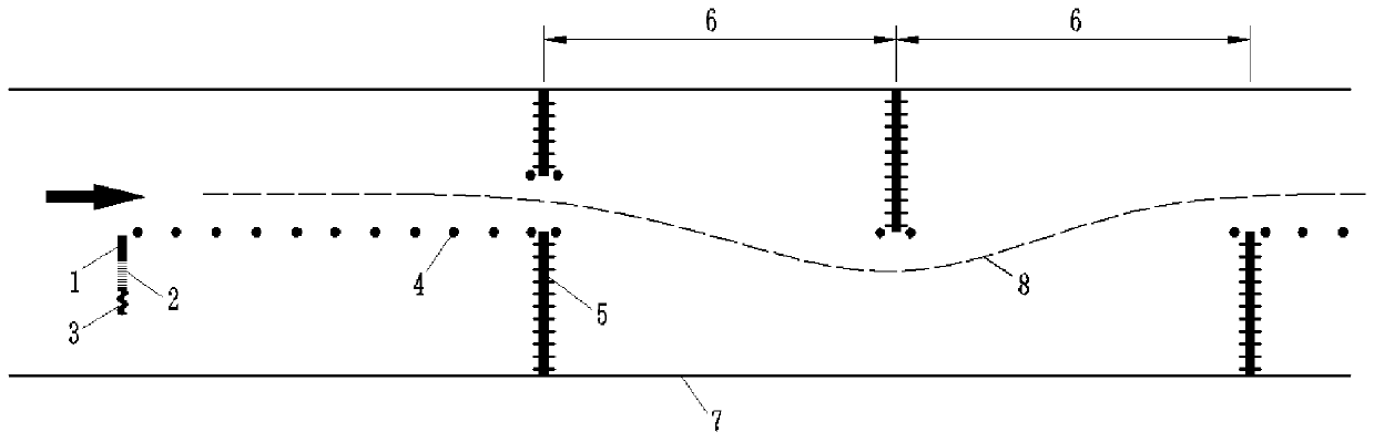
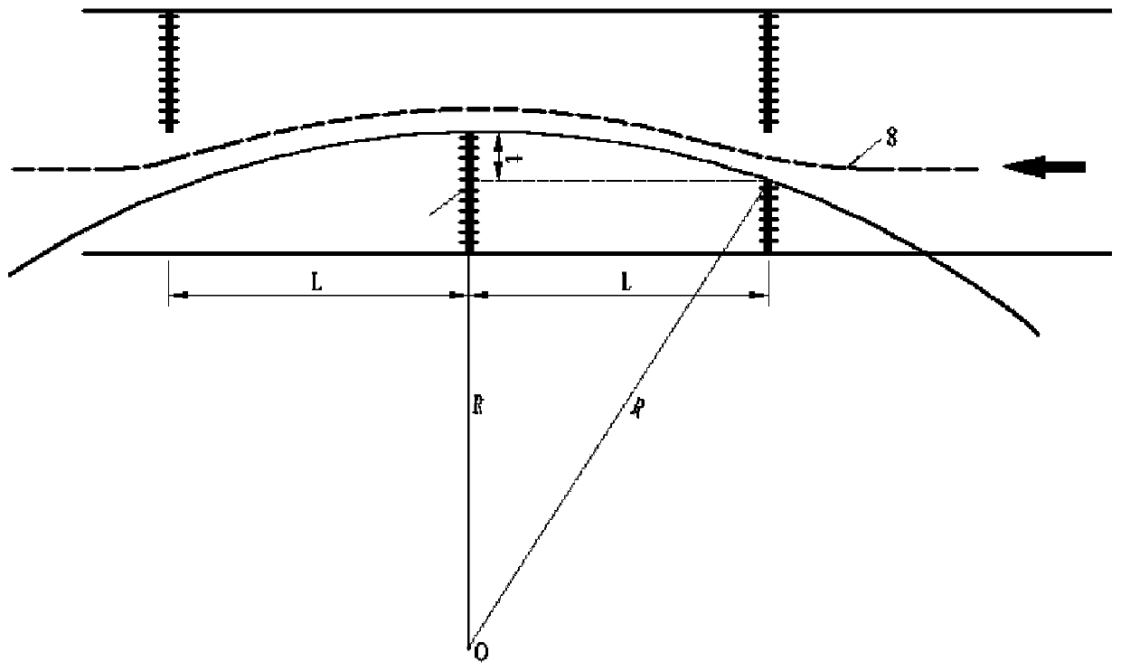
[0039] Such as Figure 1 to Figure 5 Shown, the optimal setting method of road traffic deceleration facility of the present invention is such: along the boundary 7 of the traffic lane of half-width subgrade of expressway, one section of deceleration roadblock is set, and this deceleration roadblock comprises the water barrier 5 at the entrance that arranges successively along the longitudinal direction of boundary 7 , the middle isolation section water barrier 11 and the exit water barrier 12, wherein the entrance water barrier 5 and the exit water barrier 12 are all used as roadblocks for closed traffic, and the middle isolation section water barrier 11 is used as an iso...

Embodiment 2

[0062] In this embodiment, a section of deceleration roadblocks is set every M meters along the boundary of the traffic lane; wherein, M is 300m-500m. The structure of the deceleration roadblock in this embodiment is consistent with the first embodiment.

Embodiment 3

[0064] In this embodiment, a section of deceleration roadblocks is set every M meters along the borders of several transversely parallel traffic lanes; wherein, M is 300m-500m. The structure of the deceleration roadblock in this embodiment is consistent with the first embodiment.


PUM


Abstract

The invention provides an optimal setting method for road traffic deceleration facilities. The optimal setting method comprises the steps that a deceleration roadblock is arranged along the boundary of a passing lane; the deceleration roadblock comprises an inlet water horse, a middle isolation section water horse and an outlet water horse which are sequentially arranged in the longitudinal direction of the boundary, the inlet water horse and the outlet water horse serve as roadblocks for closing traffic, and the middle isolation section water horse serves as an isolation roadblock. The inletwater horse, the middle isolation section water horse and the outlet water horse are sequentially arranged in a staggered mode and form a decelerated driving route, and therefore vehicles can be guided to drive in a decelerated mode. According to the optimal setting method of the road traffic deceleration facility, the vehicle can be reminded, warned and guided to run according to the expected route, on the basis that the running safety and comfort are guaranteed, a driver can actively reduce the vehicle speed, and therefore the running safety of the vehicle is effectively improved.

Description

technical field [0001] The invention relates to the technical field of traffic facility construction, and more specifically, relates to an optimal setting method of road traffic deceleration facilities. Background technique [0002] Vehicle speeding is one of the main causes of road traffic accidents. The speed limit of traffic management has always been a difficult problem involving public traffic safety, because it directly affects a series of issues such as road safety, traffic operation efficiency, and social and economic benefits. To limit the speed of vehicles, in addition to strengthening the cultivation of drivers' safety awareness and safety education, the current main measures include formulating mandatory administrative regulations, setting up markings and speed limit signs to remind drivers, and setting up deceleration facilities and other technologies Measures to control the speed of the vehicle. [0003] At present, for the highways and municipal roads that h...

Claims


Application Information

Patent Timeline
Patent Type & Authority Applications(China)
IPC IPC(8): E01C1/00E01F13/00E01F9/619
CPCE01C1/007E01F13/00E01F9/619
Inventor 石立万邓茹瞳汪峻峰蒋忠海
Owner FOSHAN UNIVERSITY
Why Eureka
Try Eureka