Road paver for road construction

A road construction and paver technology, applied in the direction of roads, roads, road repair, etc., can solve problems such as height difference, poor compression resistance of asphalt roads, and asphalt dilution.

Pending Publication Date: 2020-05-29
鲁开龙
View PDF0 Cites 1 Cited by
  • Summary
  • Abstract
  • Description
  • Claims
  • Application Information

AI Technical Summary

Problems solved by technology

[0005] Aiming at the deficiencies in the prior art, the purpose of the present invention is to provide a road construction paving machine to solve the problem of the prior art that the edge line cannot be well repaired, resulting in the height of the pavement of the edge line due to the height of the concrete laid and the agglomeration of the concrete. After compaction and setting, the surface will overflow with moisture and slide down along the edge, resulting in a slight height difference. After the asphalt road is laid, a large amount of water will overflow from the surface, resulting in local dilution of the asphalt. Defects of poor compression resistance of hardened asphalt roads

Method used


Image

  • Road paver for road construction
  • Road paver for road construction
  • Road paver for road construction

Examples


no. 1 example

[0029] Such as Figure 1-Figure 4 Shown, the present invention provides a kind of technical scheme of road construction paver:

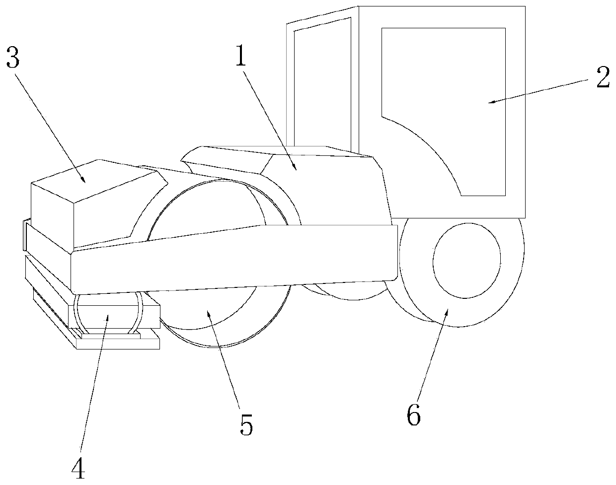
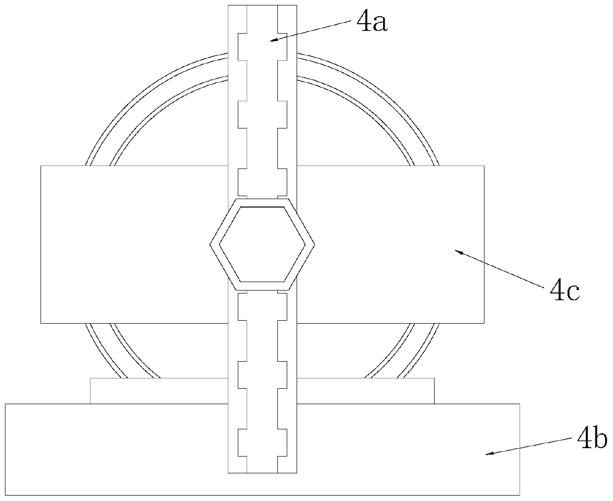
[0030] Such as Figure 1-Figure 2 As shown, a road construction paver has a structure including a car body 1, a control room 2, a driving box 3, a pressing device 4, a paving shaft 5, and a moving wheel 6. The control room 2 is installed on the upper surface of the car body 1. The rear side is connected by electric welding. The drive box 3 is installed on the front side of the upper surface of the car body 1 and connected by electric welding. The pressing device 4 is arranged on the front side of the lower surface of the car body 1 and is positioned in front of the paving shaft 5. The pressing device 4 is connected to the car body 1 by electric welding, and the moving wheels 6 are symmetrically installed on the rear side of the lower surface of the car body 1 and connected by buckling. The pressing device 4 includes an adjusting buckle plate 4a , s...

no. 2 example

[0040] Such as figure 1 , figure 2 , Figure 5 Shown, the present invention provides a kind of technical scheme of road construction paver:

[0041] Such as Figure 1-Figure 2 As shown, a road construction paver has a structure including a car body 1, a control room 2, a driving box 3, a pressing device 4, a paving shaft 5, and a moving wheel 6. The control room 2 is installed on the upper surface of the car body 1. The rear side is connected by electric welding. The drive box 3 is installed on the front side of the upper surface of the car body 1 and connected by electric welding. The pressing device 4 is arranged on the front side of the lower surface of the car body 1 and is positioned in front of the paving shaft 5. The pressing device 4 is connected to the car body 1 by electric welding, and the moving wheels 6 are symmetrically installed on the rear side of the lower surface of the car body 1 and connected by buckling. The pressing device 4 includes an adjusting buckl...


PUM


Abstract

The invention discloses a road paver for road construction. The road paver structurally comprises a vehicle body, a control room, a driving box, a smoothing and pressing device, a paving shaft and moving wheels. Beneficial effects are as follows: according to the invention, a side tightening mechanism is used; in the compaction and leveling process of the paved asphalt road, the pressing plate isused under the back-and-forth smoothing action of an elastic strip; a compact compaction effect is achieved at the side edge of the asphalt road; meanwhile, a beating plate and an arc strip are arranged on the surface, so the compacted asphalt is prevented from slipping under the action of water overflowing from internal components of the asphalt to cause the height difference at the edge of the asphalt road; according to the invention, the arranged anti-overflow structure is used for carrying out push type adsorption treatment on water overflowing from the surface of the asphalt road, so thatthe phenomena that the road is poor in compression resistance, mutual cohesion between asphalt is insufficient, and road detection is unqualified easily due to the fact that a lot of water overflowsfrom the surface of the leveled and statically stopped asphalt road are avoided.

Description

technical field [0001] The invention relates to the field of road construction equipment, more precisely, a road construction paver. Background technique [0002] When constructing roads, asphalt concrete is usually used as the material for pavement construction, and because of the long length and width of the road, in order to save labor and improve work efficiency when laying asphalt concrete , Usually road construction pavers are used for road leveling. But when utilizing this equipment for leveling, it has the following defects: [0003] The edge line cannot be well repaired, resulting in the pavement of the edge line due to the height of the paved concrete, and after the concrete is coagulated and compacted, the surface will overflow and collect water and slide down along the edge, resulting in a slight height Difference. [0004] After the asphalt road is laid, a large amount of water will overflow from the surface, which will cause local dilution of the asphalt, ma...

Claims


Application Information

Patent Timeline
IPC IPC(8): E01C19/23E01C19/26
CPCE01C19/236E01C19/264
Inventor 鲁开龙
Owner 鲁开龙
Why Eureka
Try Eureka